
|
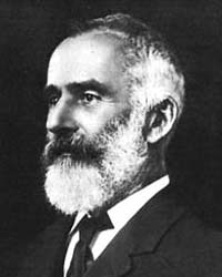 Lawrence Hargrave (1850-1915)
Australian aviation pioneer, inventor, explorer, mason and astronomer. "If there be one man, more than another, who deserves to succeed in flying through the air, that man is Mr. Laurence Hargrave, of Sydney, New South Wales. He has now constructed with his own hands no less than 18 flying machines of increasing size, all of which fly, and as a result of his many experiments (of which ,an account is about to be given) he now says, in a private letter to the writer, that: "I know that success is dead sure to come."
Octave Chanute, 1893 In 1878 he was appointed an assistant astronomical observer at Sydney Observatory, a post which he held until 1883, when he retired to devote the remainder of his life to research work into problems connected with human flight.
Flying Machine No.6, 1888 Shaw, W. Hudson and Ruhen, Olaf, 1977, p.61
In 1884 and 1892 he experimented with monoplane models, and in 1889 he constructed a rotary airplane engine, driven by compressed air.
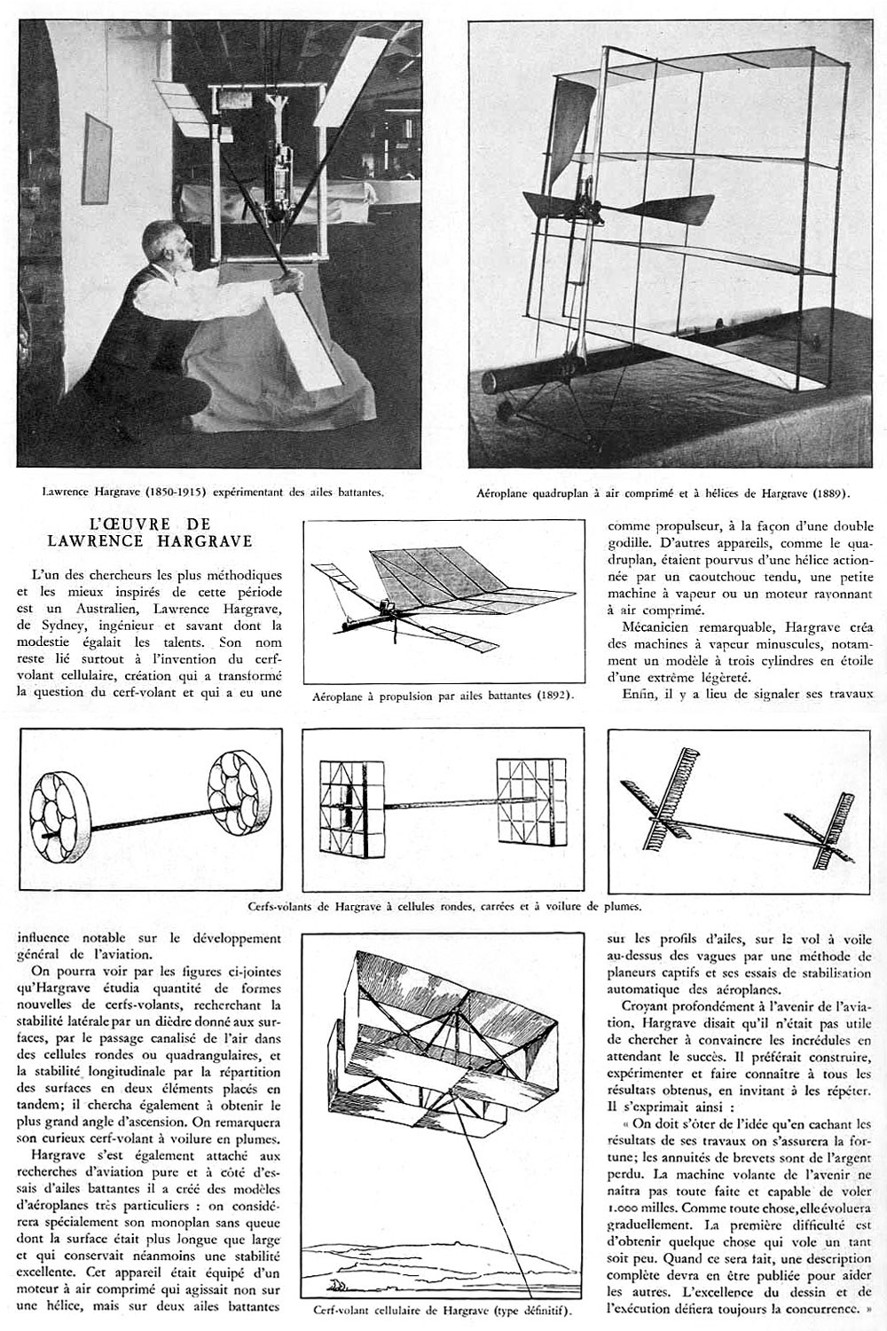
 Article on Lawrence Hargrave (image probably from 1908 based on the engine shown - Ed.) Download a 1000pixel image Philippe Gervais
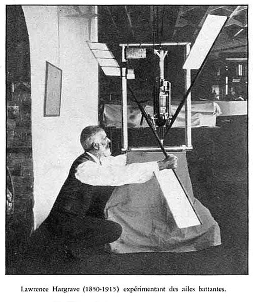 Hargrave with his Engine No.35, single-cylinder two-stroke petrol engine driving twin 'flappers', 1908 Download a 500pixel image [300dpi] Philippe Gervais
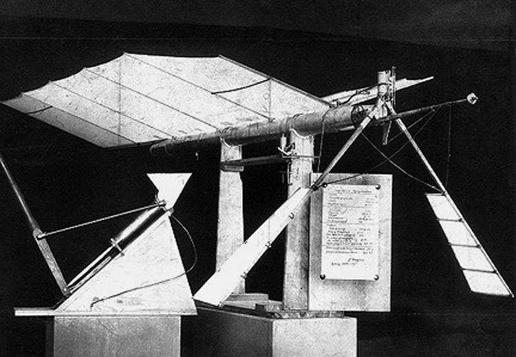
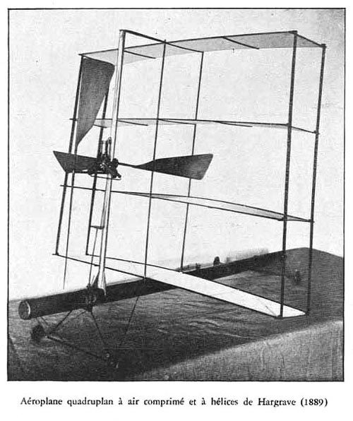 Hargrave compressed air powered 'quadraplane' (details to follow - Ed.) Download a 500pixel image [300dpi] Philippe Gervais
In 1892 Hargrave discovered that a curved wing surface appeared to give a greater lift than a flat supporting surface. Then he turned his attention to research into the behavior of various types of kites. During the course of his experiments he found out that a curved surface had twice the lift as a flat one, and next he discovered that a kite with two separated "cells" or double planes, had the greatest stability and oaring power.
 Man-carrying glider, 1893 Shaw, W. Hudson and Ruhen, Olaf, 1977, p.72
While the Wright brothers denied that they owed anything to Hargrave, his discovery of the cellular kite and his investigations into the superiority of curved wing surfaces played an important part in European experimental work which culminated in the first public flight by Santos-Dumont in France in 1906. His son and fellow experimenter, Geoffrey Lewis Hargrave, was killed at Gallipoli in May 1915, and this terrible news caused him to become seriously ill, and he died in a hospital on July 6, 1915 http://www.philately.com/philately/biohaha.htm#HargraveL
Lawrence Hargrave (1850-1915) On November 12, 1894, Lawrence Hargrave, the Australian inventor of the box kite, linked four of his kites together, added a sling seat, and flew 16 feet. By demonstrating to a sceptical public that it was possible to build a safe and stable flying machine, Hargrave opened the door to other inventors and pioneers. The Hargrave-designed box kite, with its improved lift-to-drag ratio, was to provide the theoretical wing model that allowed the development of the first generation of European (and American) airplanes. In the 1890s a small number of inventive technologists were working to translate infant aviation theory into airplanes. Leading the race was Hargrave, a quintessential nineteenth-century gentleman scientist of independent means. A gifted explorer, astronomer, amateur historian, and practical inventor, Hargrave devoted most of his life to constructing a machine that would fly. He believed passionately in open communication within the scientific community and would not patent his inventions. Instead, he scrupulously published the results of his experiments. The first successful aircraft incorporated three crucial aeronautical concepts developed by Hargrave: the cellular box-kite wing, the curved wing surface, and the thick leading wing edge (aerofoil). The Wright brothers had access to Hargrave's work through the aviation annuals published by James Means, and Octave Chanute's Progress in Flying Machines. Chanute, who corresponded with the Wright brothers, devoted a section of his book to Hargrave's experiments. But the Wright brothers, constrained by politics and patent problems of their time, admitted no influences. The direct line of Hargrave's influence on the evolution of flying is more discernible in Europe. The French (who thought that France was the cradle of aviation) freely acknowledged Hargrave's influence: Alberto Santos-Dumont was the first European to fly a heavier-than-air machine constructed of Hargrave box kites in 1906. When Gabriel Voisin built the first commercially available aircraft, based on the stable lifting surfaces of Hargrave's box kites, he called them "Hargraves." In 1889 Hargrave revolutionised engine technology by inventing the radial rotary engine, which reappeared (unacknowledged) in modified form in 1908 as the French Gnome engine. Although as early as 1892 Hargrave had voiced his opposition to the idea of the "connection of the flying machine with dynamite missiles," the rotating radial engine was extensively used in military aircraft until it was superseded by new engine technologies many years later. Hargrave's concern for the peaceful promulgation of knowledge was evidenced in his concern for the safe placement of his working models in an environment open to the public. The only museum that would meet his terms was the Deutsches Technological Museum in Munich. It is ironic that most of Hargrave's 176 working models were destroyed in the Allied aerial bombardment of Germany during World War II. The 25 surviving models were restored in the 1960s to Sydney, Australia's Powerhouse Museum, which is staging an exhibition to mark the centennial of Hargrave's first flight. Octave Chanute wrote in 1893 that "If there be one man more than another who deserves to succeed in flying, that man is Mister Lawrence Hargrave of Sydney." But Hargrave never did solve the power-to-weight ratio problem. His 1902 design was put to the test in 1992 when students at the University of Sydney rebuilt his aircraft from the original blueprint, replacing Hargrave's power plant with a modern one. ...It flew.
Progress in Flying Machines If there be one man, more than another, who deserves to succeed in flying through the air, that man is Lawrence Hargrave, of Sydney, New South Wales. He has now constructed with his own hands no less than 18 flying machines of increasing size, all of which fly, and as a result of his many experiments (of which ,an account is about to be given) he now says, in a private letter to the writer, that: "I know that success is dead sure to come." M. Hargrave takes out no patents for any of his aerial inventions, and he publishes from time to time full accounts of them, in order that a mutual interchange of ideas may take place with other inventors working in the same field, so as to expedite joint progress. He says:
"Workers must root out the idea that by keeping the results of their labors to themselves a fortune will be assured to them. Patent fees are so much wasted money. The flying machine of the future will not be born fully fledged and capable of a flight for 1000 miles or so. Like everything else it must be evolved gradually. The first difficulty is to get a thing that will fly at all. When this is made, a full description should be published as an aid to others. Excellence of design and workmanship will always defy competition."M. Hargrave is probably correct in his reasoning; for the history of all new methods of transportation teaches that the original inventor seldom receives pecuniary reward for the contrivance which is the first to succeed, but nevertheless he is certainly broadly liberal in giving to the world gratuitously the results of his constant studies and labors. He uses exceeding care in determining the different elements which compose the flight of his models. He has carefully registered the sizes of all the parts, the power consumed in each performance, and the length of the flight, together with its trajectory. He states that he has always kept his work in such shape that it could be taken up and continued by any person at any time; so that a stranger, if an expert, could come into his shop, study his notes and drawings, pick up his tools and continue his work, and thus no portion of it would be lost. M. Hargrave reports regularly the progress of his work to the Royal Society of New South Wales, of which he is a member. Thus far 13 such papers have been published, the latest having been read June 7, 1893. He first devoted his attention to the motions performed by the propelling surfaces of birds and fishes, the waves which these created in the fluids on which they acted, and the counteraction of these waves upon the forms of the propelling surfaces themselves. The first paper, therefore, presented in August, 1884, was on the Trochoided plane which M. Hargrave defines as "a flat surface, the center of which moves at a uniform speed in a circle, the plane being kept normal to the surface of a trochoidal wave, having a period equal to the time occupied by the center of the plane in completing one revolution." This was illustrated by working models, and the motions of wings and of fishes in swimming were artificially reproduced. Starting from these data, M. Hargrave next experimented with nearly 50 models intended to reproduce horizontal flight, and in exhibiting some of these and reading his second paper, June, 1885, he said:
" If the notion is not that used by birds, it is at all events very like it, and its acceptance or rejection as a scientific truth is of no further interest, as it only remains for practical mechanics to step in and adjust the details to suit the material and the motive power which they may think best for the purpose they have in view; or, in other words, that the solution of the problem of just how a bird flies is of very trifling importance from a practical standpoint, as compared with the judicious variations of the parts of the machine that will have to be made before any return can he expected for money invested in such undertakings."Some of these models seem to have been driven by clock-work, and the motions were those of the "trochoided planes," as applied to flapping wings; then selecting the best of these models, and making their mean dimensions a standard from which to take a fresh departure, M. Hargrave next built a series of experimental flying machines actuated by india-rubber in tension. The French experimenters, as we have seen, have preferred to use rubber in torsion in order to diminish the strains upon the central spine or backbone of the model but they thus obtained less energy per pound of weight than if they had used it in tension. M. Hargrave stretched the rubber so that its elongation was multiplied by pulley tackle, and that, as the rubber contracted, its center of gravity moved forward, thus advancing the center of gravity of the entire machine, and consequently diminishing the angle of flight as the force of the rubber decreased. No less than 10 different flying machines of various types were thus built and experimented with, all moved by rubber in tension In the first models the cord proceeding from the rubber was wound around a cylindrical drum on the crank-shaft, but owing to the variable resistance natural to a crank-shaft, it was found better to replace the cylindrical drum by a flat winder, so adjusted on the shaft that the moment of the cord varied with the resistance of the crank, and thus communicated a more uniform movement to the wings. Seven of these machines seem to have been propelled by flapping wings--i.e., "trochoided planes"--but in order that a comparison might be made, three varieties of models were made with screw propulsion--namely, with double and with single screws in the bow, and with a single screw in the stern, which latter was concluded to be the most practicable and serviceable form. From these experiments M. Hargrave concluded that the screw and the flapping wings are about equally effective as instruments of propulsion, although he rather prefers the latter, as the wings possess several marked advantages. Any currents, he says, initiated during the upstroke are utilized in giving increased efficiency to the down-stroke, if the machine has not progressed far enough to be acting upon entirely undisturbed air. Moreover, when steam-engines come to be used, there will be only one cylinder needed for both wings, there will be no conversion of reciprocating into rotary motion, and no variable listing moment to be counteracted, while, finally there is less liability that wings shall be damaged in alighting than screw blades Fig. 76 shows the last one (1889) of the india-rubber driven machines described by M. Hargrave He calls it the "48 band-screw." The screw is at the stern, and the machine weighs exactly 2 lbs. Its sustaining area is 14.51 sq. ft. (7.26 sq. ft. per pound), and it flew 120 lineal feet with the expenditure of 196 foot-pounds of energy, while the preceding machine, weighing 2.09 lbs., with flapping wings, had flown 270 ft. with 470 foot-pounds, thus showing respectively 0.61 and 0.57 lineal feet flown per footpounds of power. The framework of these machines was of pine, the larger piece (main spine) being a hollow box-girder, to secure strength and lightness. The sustaining surfaces were of paper, pasted on, and after the gum was dry rendered as tight as a drum by blowing a light spray of water over the paper and allowing it to dry. Thus with small, light, simple, and inexpensive models many experiments were made. and great advance realized in the distance flown over any previous experiments of others. Having progressed thus far with india-rubber as a motive power, and gathered most valuable data and experience: as to the best arrangement and proportion of parts, the equipoise and the power required, M. Hargrave next undertook the construction of a flying machine actuated by compressed air, and, in 1890. he produced the machine illustrated by fig. 77, which he calls his "No. 10 40 5 oz. compressed air," and which marked a very considerable advance in design by a great simplification of the propelling arrangement. In presenting it to the Royal Society, June 4, 1890, M. Hargrave said:
"The principle embodied in this experiment is that of Borelli, published in 1680, and it doubtless has had many stanch advocates in later times; but the writer maintains that this is the first practical demonstration that a machine can and does fly by the simple (vertical) flapping of wings; the feathering, tilting, twisting, trochoiding, or whatever it may be called, being solely effected by torsional stress on the wing arms.This machine flew 368 ft., with the expenditure as corrected by M. Hargrave of 870 foot-pounds of energy. It weighed 2.53 lbs., and the sustaining body plane measured14.78 sq. ft., while the two wings measured 1.50 sq. ft. in area, making a total of 16.28 sq. ft., or, say, 6 .43 sq. ft. per pound. London Engineering, in its issue of December 26 1890, gives the following description of the machine:
"The compressed air is stored in a tube which forms the backbone of the whole construction. This tube is 2 in. in diameter, 48 1/4 in. long, and has a capacity of 144.6 cub. in. Its weight is 19.5 OZ., and the working pressure is 230 lbs. per square inch. The engine cylinder has a diameter of I! in. and a stroke of II in., while the total weight of the engine is only 6 1/2 oz. The piston-rod is made fast to the end of the backbone, and the cylinder moves up and down over the piston. Two links connect the cylinder to the Canadian red pine rods which carry the wings. The air is admitted to the cylinder and exhausted by means of a valve worked by tappets. The period of admission continues through the entire stroke. The cylinder and receiver ends are pressed, and the piston is made of vulcanite, with a leather cup ring for packing.It will be noted that the engine is a marvel of simplicity and lightness. Its cylinder is made like a common tin can, the cylinder covers are cut from sheet tin and pressed into shape in a vice, the piston and junk-ring are made of vulcanite, and the cup leather packing does away with the necessity for the cylinder being either round or parallel. Beside the engine, a marked advance consisted in securing the torsion of the wings through no special mechanism, as formerly, but simply by the elasticity of the material composing them. This throws a new light upon the part performed in the flight of birds by the elasticity of their feathers, and promises great simplicity and efficiency in the future designing of artificial wings. By looking at the figure, a bowsprit will be noticed. This was a so-called safety stick, which was added to break the fall of the machine when alighting, and it has proved quite successful in accomplishing that object. A noticeable feature of this and subsequent machines exhibited by M. Hargrave consists in the extraordinary length of its supporting body plane, The same surface would carry a far greater load if it were driven broadside instead of lengthwise; but M. Hargrave explains that the plane was purposely so designed in order to insure longitudinal stability. This quality might also be secured by placing a tail far in the rear of a narrow supporting plane, as practiced byPénaud and others. He states, moreover, that the plane is rendered more effective per unit of surface by being cut away in the middle portion, or by being formed in two parts, separated by a gap. As regards the lateral equilibrium, he seems to have met with but little difficulty a slight diedral angle of the two halves of the body plane with each other providing the necessary stability, and preventing any swerving, so long as the center of gravity was at all below the center of effort; but he had great trouble in working out the longitudinal stability. This he did upon the "cut and try" principle--a method doubtless the most thorough, the surest, and the most convincing, but also the most tedious. He found that the direction up or down of the machines in flight was entirely due to the distance of the center of gravity from the forward edge of the body plane, and therefore to the coincidence or otherwise of the center of gravity with the center of pressure. He measured the percentage of area in advance of the center of gravity in his three most successful machines, and found it respectively 19.3, 20 and 23.3 per cent. of the length of the plane, while subsequently he came to the general conclusion that the true position for the center of gravity for a continuous rectangular surface is situated between 0.25 and 0.2 of the length from the forward end, these positions being arrived at "by experience gained by repeated wrecks when groping in comparative darkness." This independent working out of a complex question well illustrates the perseverance and ingenuity of this experimenter. At this juncture, however, he would have been saved much groping, time, and annoyance had he been aware of the formula of Joessel for determining the center of pressure:
C = (0.2 + 0.3 sin.a) L, in which C is the distance from the forward edge of a rectangular plane to its center of pressure, when inclined at the angle of incidencea with the course, and L is the length of the plane along the line of motion. In the same year (1890) M. Hargrave built another flying machine, actuated by compressed air and propelled by beating wings. This is shown by fig. 78. It was of the increased weight of 4.63 lbs., with sustaining body plane of different shape, measuring 29.63 sq. ft., or in the proportion of 6.40 sq ft. per pound. It flew 343 ft., with an expenditure of 789 foot-pounds of energy, and therefore showed better results than the previous machine (No. 10), inasmuch as more pounds were transported on the air approximately the same distance, with a somewhat smaller expend ture of energy. Having apparently found some advantage by shortening the body plane, M. Hargrave next built his flying machine No. 13, which shown in fig. 79, with a body plane still shorter, and he provided it with a two-bladed aerial screw, set in the bow and actuated by a three-cylinder compressed-air engine of the Brotherhood type. This drove it 128 ft. in eight seconds, with an expenditure of 143 footpounds of energy. The apparatus weighed 46.86 oz. (2. 93 lbs.), and exposed 2952 sq. in. or 20.5 ft. of floating surface, being in the ratio of 7.00 sq. ft. per pound. This is the first time (paper 10, July 1, 1891) that M. Hargrave gives us the time of flight of his machines, so that we may calculate the number of pounds of weight transported in ratio to the horse power. He says:
"The time of flight is taken with a sandglass which has a ]orp of string at each end of it. The loop at the sand end is put round the right wrist, and the other loop is held between the right thumb and the receiver, so that the glass is turned the moment that the machine is let go. On the machine taking the ground the glass is put horizontal, and the sand which has fallen is timed at leisure. This seems an obvious enough method of finding the speed, but a practical way to do it was not devised previously."This showed for No. 13 machine a speed of 10.34 miles per hour which is about what we should have expected from the large proportional surface, it being about in the ratio of the slowest flying birds. This low speed M. Hargrave adopts on purpose, the better to observe the motions of the machines and to save breakage, and he adds quaintly that he sees no objection to this course, so long as the atmosphere is not crowded with flying machines. As No. 13 machine (fig. 79) is reported as having expended 143 foot-pounds in eight seconds, we have:
Power = 143 ˜ 8 = 18 foot-pounds per second, nearly, and, as it weighed (as reported) 2.93 lbs., we have for the weight sustained per horse power: 2.93 X 550 ˜ 18 = 89.53 lbs. per horse power; while it will be recollected that M.Tatin sustained 110 lbs. per horse power and that M.Phillips in his recent (1893) experiments floated 72 lbs. per horse power We will see by the analysis of subsequent performances that M. Hargrave did not obtain quite as good results with subsequent flying machines. He next built his No. 14 flying machine, with much the same shape of body surface, but propelled by beating wings instead of a screw. It weighed 3.69 lbs. and exposed 22.84 sq. ft. of surface, being in the proportion of 6.19 sq. ft, per pound. It flew 312 ft. in 19 seconds, with an expenditure of 509 foot-pounds, and thus we have: Power = 509 ˜ 19 = 26.79 foot-pounds per second and for the weight floated per horse power:
3.69 X 550 ˜ 26.79 = 75.75 lbs. per horse power. This apparatus (No. 14) M. Hargrave has generously offered to present to some American institution which will take proper care of it, believing it to be one in which "the increased skill in construction acquired by practice is thought to have resulted in an apparatus that, for its weight, it will be hard to excel." He says in his paper to the Royal Society:
"It may be said that it is a waste of time to make machines of such small capabilities, and that no practical good can come of them. But we must not try too much at first; we must remember that all our inventions are but developments of crude ideas; that a commercially successful result in a, practically unexplored field cannot possibly be got without an enormous amount of unremunerative work. It is the piled-up and recorded experience of many busy brains that has produced the luxurious travelling conveniences of to-day, which in no way astonish us, and there is no good reason for supposing that we shall always be content to keep on the agitated surface of the sea and air, when it is possible to travel in a superior plane, unimpeded by frictional disturbances."No 16 was another compressed-air flying machine with beating wings and somewhat differently shaped body plane. It weighed 4.66 lbs., spread 26.06 sq. ft. of surface, and flew 343 ft. in 23 seconds, with an expenditure of 742 foot-pounds. The power was therefore:
Power = 742 ˜ 23 = 32.26 foot pounds per second, and the weight floated per horse power:
4.66 X 550 ˜ 32.26 = 79.45 lbs. per horse power. Several forms of body plane seem to have been tested in this machine and no less than 12 trials were recorded, trial No. 10 being the successful one, from which the above data have been taken. Having now constructed 10 flying machines of different types and proportions actuated by mafia-rubber in tension, and six actuated by compressed air, of increasing size and weight, M. Hargrave then turned his attention to producing a steam motor which should equal in lightness and surpass in power the best compressed-air motors thus far constructed by him, and which should furnish driving power for a longer time. But first he endeavored to work out an idea which he seems to have entertained for some years, of testing an explosion motor. His engine No. 15 consisted of a turbine to be worked by the gases resulting from the explosion of a mixture of nitrate of ammonia, charcoal, and sulphur; but a considerable expenditure of time only resulted in a failure. He also experimented upon a method of utilizing sea waves in propelling vessels, which he believes to be the germ of the solution of the soaring problem, and he succeeded in securing such automatic action that a 12 1/2 lb. mode advanced in the winds eye at five-eighths of a mile per hour. He also made some experiments upon pure aluminum, but found that it presented no advantages for flying machine construction.
The boiler is of the "Serpollet" type, made of 12 lineal feet of 1/4 in. copper tubing (steel pipe could not be got in Sydney), in the form of a double-stranded coil, encased in asbestos, and placed just over the backbone of the apparatus. The fuel is methylated spirits of wine, drawn from a tank placed above the boiler, vaporized, mixed with air and spurted into the furnace. As much as 6 .9 cub. in. of water have been evaporated by 1.7 cub. in. of spirit in 80 seconds, making 182 double vibrations of the propelling wings, say, 2.35 per second, and developing 0.169 horse power. It was estimated that if the apparatus were loaded with 10 oz. more of spirit and water, and thus made to weigh the same as the compressed-air machine No. 12, which flew 343 ft., then the steam apparatus No. 17 would possess a sufficient store of energy to fly 1640 yds., or nearly 1 mile. But M. Hargrave has done still better, for in March 1893, he prepared a paper, which was presented to the Conference on Aerial Navigation at Chicago, August 2 1893 in which he gave data concerning his No. 18 flying machine. This apparatus is also driven by a steam-engine which weighs, with 21 oz. of fuel and water, an aggregate of 7 lbs, and indicates 0.653 horse power, or at the rate of 10.7 lbs. per horse power; so that, roughly speaking, the weight of the motor has been doubled, and the power has been increased fourfold. Four boilers were constructed. The final one was made of 21 lineal feet of 1/4 in. copper pipe, with an internal diameter of 0.18 in., and arranged in three concentric vertical coils whose diameters were 1.6 in., 2.6 in., and 3.6 in. respectively. It weighed 37 oz., but it is now known "that a coil of equal capacity can be made weighing only 8 oz, and still excessively strong." The cylinder is 2 in. diameter with a stroke of 2.52 in. The feed-pump ram is 0.266 in. diameter, and the piston valves 0.3 in. diameter. On one occasion this motor evaporated 147 cub. in. of water with 4.13 cub. in. of spirit in 40 seconds. During a portion of the time it was working at a speed of double vibrations per minute. M. Hargrave gives no data concerning the flight of his last two (steam) machines. He states that 11 different burners have been tried, and that the flame striking the water boiler first has a tendency to vary the supply of heat to the spirit holder. From this it is inferred that he is struggling with the same difficulties already encountered by Stringfellow, by Moy, and by Maxim in regulating and keeping alight spirit burners when the apparatus gets under forward head-way; but this difficulty, while a serious one, will doubtless be eventually overcome by persistent experiment, and we may then expect flights of astonishing lengths. Seeing now his way to an adequate motor and to extensive flights in the near future, M. Hargrave recently turned his attention to experiments upon curved surfaces, and to the seeking for a better disposition of the sustaining surfaces or body planes. He had described the eccentricities of a curved strip in the form of a segment of a hollow cylinder, when exposed to the wind, in his paper No. 12 to the Royal Society of New South Wales, read August 3, 1892 and he describes some of his experiments with "cellular kites," in his paper read in the Aerial Navigation at Chicago, August 2 1893. The "cellular kites" constitute quite a new departure, and practically consist of superposed aeroplanes connected together in pairs. B, in fig. 80, shows the simplest form. This consisted of two hollow cylinders of aluminum, each 13 in. diameter by 4 1/2 in. deep, mounted 30 in. apart upon a connecting stick, and weighing 14 3/4 lbs. The kite-string was attached 11 in. back from the forward section, and as a consequence of the angle of incidence thus produced, the apparatus mounted upon the wind. Its particular behavior is not described in the paper. C, in fig. 80, shows a kite with 16 cells, the length of each being 3 in., by a height of 3 in., and a breadth of 3 in. It was made of cardboard, and the two sections were 22 in. apart, the point of attachment of the kite-string being 6 1/2 in. distant from the forward section, while the weight was 10.5 lbs. This seems to indicate that this kite flew at a steeper angle than the preceding, although we should expect the reverse, in consequence of the greater proportion of sustaining surface. M. Hargrave says,
"These kites have a fine angle of incidence, so that they correspond with the flying machines they are meant to represent, and differ from the kites of our youth, which we recollect floating at an angle of about 45 , in which position the lift and the drift are about equal. The fine angle makes the lift largely exceed the drift, and brings the kite so that the upper part of the string is nearly vertical."Kites E and F, fig. 81, are of exactly the same size and weight, consisting of one cell, 4 in. long, 10.7 in. broad by 6.25 in. high, constructed of wood and paper, and weighing 3.25 lbs.; the two sections are 21.25 in. apart, and the string is fastened 7.25 in. back of the forward section. The only difference is that kite E has its horizontal (top and bottom) surfaces curved to a radius of 4.5 in. while all the surfaces of kite F are true planes, The result is that when kite E is flown with the convex sides up it pulls about twice as hard on the string as kite F, so that, as M. Hargrave says:
"A flying machine with curved surfaces would be better than one with a net body plane, if the form could be made with the same weight of material."M. Hargrave in this last paper, figures and describes two other forms of cellular kites with which he has experimented, and points out that the rectangular form of cell is collapsible when one diagonal tie is disconnected. so as to make it easy of transportation. He says:
"Theoretically, if the kite is perfect in construction and the wind steady, the string could be attached infinitely near the center of the connecting stick, and the kite would fly very near the zenith. It is obvious that any number of kites may be strung together on the same line, and that these is no limit to the weight that may be buoyed up in a breeze by means of light and handy tackle. The next step is clear enough--namely, that a flying machine with acres of surface can be safely got under way, or anchored and hauled to the ground by means of the string of kites."He duly gives credit to M. Wenham for suggesting the superposition of planes in 1866 and it is an interesting circumstance to note that at the same Chicago Conference, a paper from M. Wenham was read suggesting a course of experiments with kites, to determine the best arrangement of superposed aeroplanes and the conditions of equipoise. Such are the labors of M. Hargrave to the present time. He no longer troubles himself about the general problem of man's eventual success in navigating the air, but he says:
"The people of Sydney who can speak of my work without a smile are very scarce; it is doubtless the same with American workers. I know that success is dead sure to come, and therefore do not waste time and words in trying to convince unbelievers."Instead of this, he constructs machines and reports the results in detail, so that others may repeat his experiments. He e says that the record of unsuccessful experiments takes up a considerable portion of kits notes, and further, that "there is no use in the mind's conceiving an idea, if the hands are not ready to carry out the work skillfully, in the absence of reliable assistance, and if the design be found faulty, the whole thing should be begun again without trying to use up old machines. The question of intricate workmanship and costliness is being continually battled with; my constant endeavors are directed to making the machines simple and cheap, so that any one who doubts can verify my work, provided his hands are as skillful as mine, and I am sure that the photographs show clearly that the workmanship is anything but first-rate. He began with small, cheap models, and has gradually enlarged their size, and obtained flights longer than any heretofore accomplished. It is noticeable that the heavier the model, and the smaller the sustaining area in proportion to the weight, the more successful has been the flight. He may not be the first man to ride at will upon the air, but he deserves to succeed. Octave Chanute, 1893
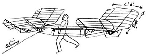
Hargrave Kite Dan Beard In 1884 Mr. E. Douglass Archibald, of the Royal Meteorological Society, sent up two diamond-shaped kites, one seven feet and the other four feet in diameter, both attached to one string. These kites, like Ben Franklin's, were covered with silk; they carried scientific instruments 2,200 feet into the air. "Pshaw," said some Americans, "how is this for high?" and they sent a tandem team of kites 6,000 feet up in the air; over a mile high! That is kite flying! Why, if any one of the boys had been able to do such a thing when the author was a lad flying kites on the banks of the Ohio River, that boy would have achieved fame enough to satisfy even the vaulting ambition of a young Ben Franklin. The writer's experiments had no scientific ends in view; his mission was to introduce new shapes of kites and prove by experiment that they would fly. He felt more pride in holding by main strength the heavy hemp twine to which a six-foot, straddle-legged-man kite was attached than ever was experienced by any, of those learned professors with their tandems of tailless kites loaded with scientific instruments. But all boys will be interested in Lawrence Hargrave's kites. This great Australian inventor of flying machines wanted some sort of an apparatus from which to send off his flying machine, and so he invented... The Strangest Kite Ever Made In appearance there is nothing to suggest a kite; but then this is not surprising in a country where moles have the bills and feet of ducks and are credited with laying eggs, where poll-parrots kill sheep, and where natives have war clubs which when thrown at an enemy not only knock the enemy over but immediately return to their owners' hands. If the inhabitants of such a country fly kites we expect something unheard of in the kite line, and Lawrence Hargrave's kites do not disappoint us. Imagine two boxes with their sides removed and connected by rods and you have the form of the Hargrave kite. Mr. Hargrave calls these boxes "cells," but you must not mind that any more than you do when Mr. Eddy, Mr. Woglom and Professor Clayton call their kites "aero-planes." They mean all right by it. After you grow up to man's estate and dignity, you too will be hunting up out-of-the-way terms for common things. But now, while you are boys, be charitable to the poor men and let them keep their dignity with big words, while you use simpler ones which answer the purpose better. Mr. J. B. Millet Tests its Qualities. Mr. Millet spent three summers experimenting with the Malay or Eddy kite and then constructed a Hargrave kite, and seems to be well satisfied with the action of this double dry-goods box, for that is what it most resembles. Mr. Millet, in comparing the Hargrave with the Holland, Malay, or Eddy in the Aeronautical Annual, No. 2,1896, says that "the Hargrave was the steadier, the less likely to break or lose its shape in the air, and lifted much more per square foot of lifting surface." He further says that it is a kite that can be anchored in the wind and left there without fear of disaster. It will fly steadily and not require constant mending or balancing. It is evident a glance that the Hargrave kite must possess "rigidity, of frame. It is also evident that this is a most difficult quality to be secured without adding weight to the structure. Hence this kite is generally considered as unfit for light winds. How to Make a Hargrave Kite Take eight slender, stiff pieces of bamboo, what the inland boys know as fishin' pole or cane. These sticks must be as evenly balanced as possible and exactly the same length, eighteen inches and three-quarters long. Next cut six sticks each eleven inches long and as nearly alike as possible. These are for the middle uprights and end stretchers. Find the middle of each of your first eight sticks and lash them together in pairs at their middle (Fig. 33 A). Use waxed shoe-thread to bind the middle points together, and make the spread between a and c just eleven inches. Notch the ends of the stick.
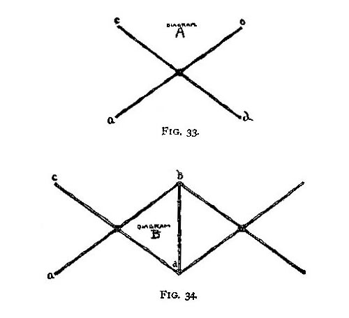 Fig. 33, 34
You now have four pairs of cross sticks neatly fastened together, and you must take one of your eleven-inch uprights and bind it to the ends of two pairs of cross sticks (Fig. 34 B). Take the other eleven-inch upright and fasten the other two pairs of cross sticks in the same manner. Next cut two "booms," "spines," or connecting-rods, also of stiff bamboo, and let them each be thirty inches long, and like the two uprights, as nearly alike as it is possible for you to select them. Now, with your waxed thread, or shoe thread, bind the two booms over the ends of the eleven-inch stretchers or uprights (Fig. 35 C). The boom must fit like the top of a letter T over the stretchers, and be perfectly square, that is, at right angles with the stretcher, b, d, Fig. 34 B.
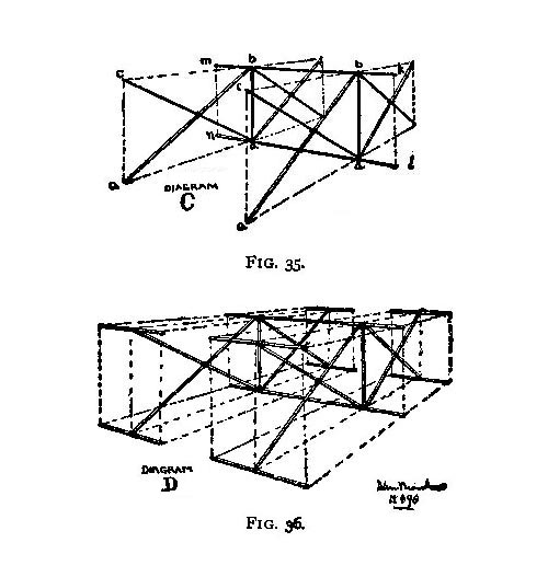 Fig. 35, 36
Each end of the booms must protrude beyond the uprights five and one-half inches, that is, the end b, k, the end d, l, the end m, b, and the end a, n, must each be five and one-half inches long, which leaves nineteen inches between b, b and d, d (Fig. 35 C). Bind the other four stretchers to the ends of the sticks a, c, etc., as shown in Fig. 36 D. Now string the frame, so that all the sticks (with the exception of the diagonal or cross sticks, Fig. 33 A) shall be, as the boys say, perfectly square with each other or, more correctly speaking, at right angles. Take an old paint-brush and a pot of hot glue, and paint all the joints with glue.
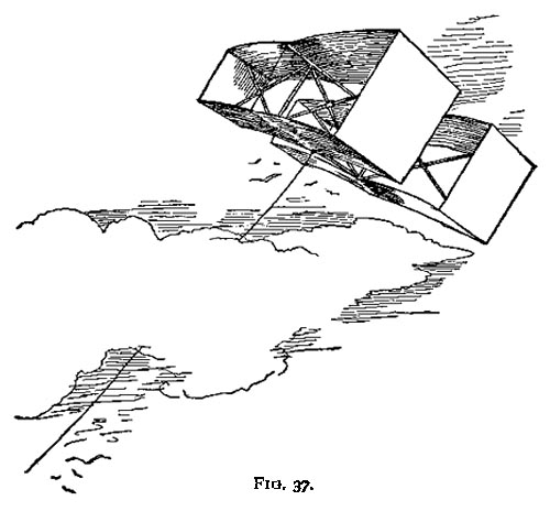 Fig. 37
The frame is now finished, and it only needs a cover. The frame should now measure thirty inches in the longest dimension of the box or cell, eleven inches in the height of the cell, and eleven inches in the breadth of the cell, that is, 11 by 11 by 30 inches for each box or cell, and thirty inches for the length of the two booms, and eight inches between the cells. Cover the kite with light, strong cloth that will not stretch. Fit the cloth over the frame neatly, and sew it on so as to form two boxes covered at the top, bottom, and ends. But the two broad sides of each are left open for the wind to whistle through. Hem all the raw edges of the cloth. On the bottom boom, at or near the inside edge of the cloth cover, lash with waxed thread a small brass ring for a belly-band (Fig- 37).
Flying Machines: Construction and Operation
Chapter I. Evolution of Two Surface Flying Machine : Renard's "Dirigible Parachute" I am asked to set forth the development of the "two-surface" type of flying machine which is now used with modifications by Wright Brothers, Farman, Delagrange, Herring and others. This type originated with Mr. F. H. Wenham, who patented it in England in 1866 (No. 1571), taking out provisional papers only. In the abridgment of British patent Aeronautical Specifications (1893) it is described as follows:
Two or more aeroplanes are arranged one above the other, and support a framework or car containing the motive power. The aeroplanes are made of silk or canvas stretched on a frame by wooden rods or steel ribs. When manual power is employed the body is placed horizontally, and oars or propellers are actuated by the arms or legs. A start may be obtained by lowering the legs and running down hill or the machine may be started from a moving carriage. One or more screw propellers may be applied for propelling when steam power is employed.On June 27, 1866, Mr. Wenham read before the "Aeronautical Society of Great Britain," then recently organized, the ablest paper ever presented to that society, and thereby breathed into it a spirit which has continued to this day. In this paper he described his observations of birds, discussed the laws governing flight as to the surfaces and power required both with wings and screws, and he then gave an account of his own experiments with models and with aeroplanes of sufficient size to carry the weight of a man. ...and as it applies to Lawrence Hargrave... [Ed] Hargrave's Kite Experiments After experimenting with very many models and building no less than eighteen monoplane flying model machines, actuated by rubber, by compressed air and by steam, Mr. Lawrence Hargrave, of Sydney, New South Wales, invented the cellular kite which bears his name and made it known in a paper contributed to the Chicago Conference on Aerial Navigation in 1893, describing several varieties. The modern construction is well known, and consists of two cells, each of superposed surfaces with vertical side fins, placed one behind the other and connected by a rod or frame. This flies with great steadiness without a tail. Mr. Hargrave's idea was to use a team of these kites, below which he proposed to suspend a motor and propeller from which a line would be carried to an anchor in the ground. Then by actuating the propeller the whole apparatus would move forward, pick up the anchor and fly away. He said: "The next step is clear enough, namely, that a flying machine with acres of surface can be safely got under way or anchored and hauled to the ground by means of the string of kites." The first tentative experiments did not result well and emphasized the necessity for a light motor, so that Mr. Hargrave has since been engaged in developing one, not having convenient access to those which have been produced by the automobile designers and builders. Experiments With Glider Model And here a curious reminiscence may be indulged in. In 1888 the present writer experimented with a two-cell gliding model, precisely similar to a Hargrave kite, as will be confirmed by Mr. Herring. It was frequently tested by launching from the top of a three-story house and glided downward very steadily in all sorts of breezes, but the angle of descent was much steeper than that of birds, and the weight sustained per square foot was less than with single cells, in consequence of the lesser support afforded by the rear cell, which operated upon air already set in motion downward by the front cell, so nothing more was done with it, for it never occurred to the writer to try it as a kite and he thus missed the distinction which attaches to Hargrave's name. Sir Hiram Maxim also introduced fore and aft superposed surfaces in his wondrous flying machine of 1893, but he relied chiefly for the lift upon his main large surface and this necessitated so many guys, to prevent distortion, as greatly to increase the head resistance and this, together with the unstable equilibrium, made it evident that the design of the machine would have to be changed.
Further Reading A Hargrave Gallery 1850 - 1915 'The Air Age' : The Man Who Made It Possible Hargrave Papers : Royal Soc. of NSW
|
© Copyright 1999-2002 CTIE - All Rights Reserved - Caution |