
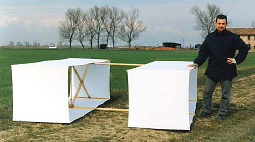
Hargrave Box Kite Replicaby Andrea CasalboniKiting historian and Editor of the fine Italian kiting website KITES!
Materials
To begin with we must build the main kite structure which is composed of 2 longitudinal longherons and the 4 cross-spars. We start with the 2 rods of dimensions 28 x 28 x 2440 mm which are the 2 main longitudinal longherons.
 upper longitudinal longherons a larger copy of this image may be downloaded
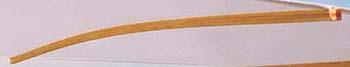
The central part of these 2 spars must be rounded off, while at about 30 cm from each of their respective ends, they must be thinned in height.
 longitudinal longheron a larger copy of this image may be downloaded
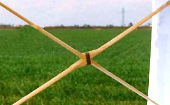
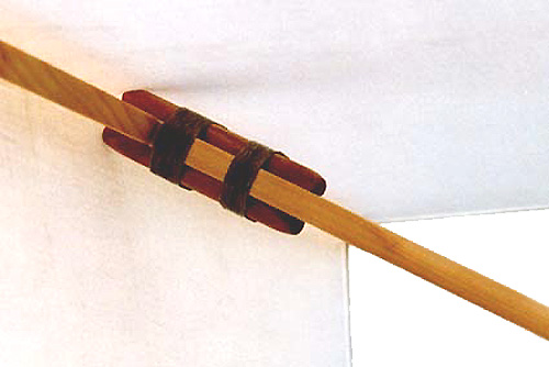
At a distance of 42 cm from the ends we must create 2 lock slot of roughly 35mm and with a slope of approx. 60 degrees. The ends of the cross spars will be required to fit into these lock slot.
 lock slot in the longitudinal longherons a larger copy of this image may be downloaded
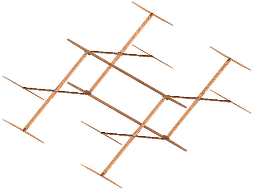
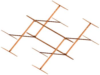 structural drawing of the complete kite a larger copy of this image may be downloaded
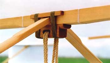
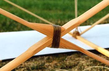
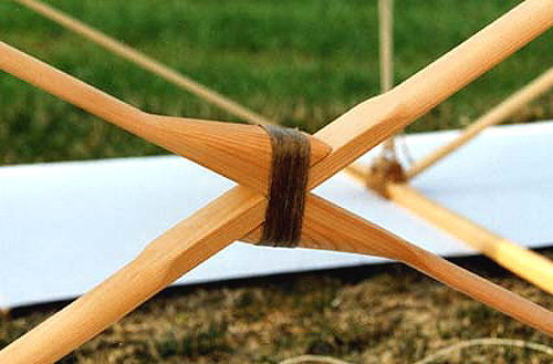
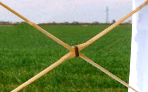
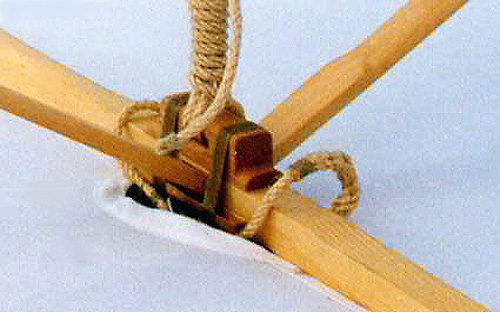
Next we proceed to the construction of the structure through which the binding ropes pass. For this we use the 30 x 28 x 120 mm beech rods. These rods must be shaped so as to create a cavity which will support at least twice the amount of binding rope. In addition it becomes necessary to use the 10 x 10 x 120 mm beech rods which will function as a support for the cross spars. All these parts are to be rounded toward their ends so as not to have any sharp corners which might otherwise cut the binding ropes. The binding is actually performed after the various parts are glued together. For the binding we use hemp of approx 1mm diameter. We suggest that the hemp be immersed in water prior to being used so as to prevent a lengthening once the final structure is constructed. When this binding becomes dry we can place a layer of vinyl glue on top to bind the whole structure.
 tensionatore a larger copy of this image may be downloaded
 appoggio crociere a larger copy of this image may be downloaded
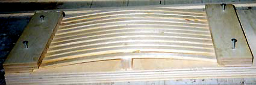
Construction of the wing ribs These wing ribs must be assume a curved shape. To realize this wing ribs is necessary to create a forming die (stamp) for ensuring that an equal curvature results in all the sticks. This structure may be simply constructed using a board (plank) 20-30 cm long and roughly 90 cm in length.
 forming die for the curvature of the wing ribs a larger copy of this image may be downloaded
At the center of this board, and perpendicular to it, we fix a rod of 28mm thickness and 10mm width. This rod will determine the exact height of arc described by the rods. In order to maintain the wing profile sticks curved, it is necessary to overlay 3 layer of rods of dimensions 4 x 12 x 840mm glued together by means of vinyl glue. The packet of rods is placed on the structure, the crossing previously fixed being placed exactly in the middle of the sticks afterwhich the ends of the sticks are fixed to the table by means of clamps. In this way we curve the sticks and once the glue has dried we shall have achieved an arc which is precise and stable with respect to time.
 wing rib a larger copy of this image may be downloaded
 a finished wing rib attached to the sail a larger copy of this image may be downloaded
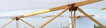
Construction of the cross spars These sticks are composed of 3 parts for each cross member: the main stick of 1500mm length, and the other 2 of 748 mm length. The main stick additionally supports the 2 support blocks of the secondary sticks.
 first cross spar a larger copy of this image may be downloaded
 secondary cross spars a larger copy of this image may be downloaded
 support blocks for cross spar a larger copy of this image may be downloaded
 completed cross spar a larger copy of this image may be downloaded
All the sticks are to be tapered from 55mm from the center up to 35 mm from one ends. Additionally, they must be shaped so as to create a load-bearing profile with flat underside and curved upperside. To the main stick are attached the two 30 x 55 x 135mm fir rods which must first be cut to 60 degrees on the side on which the secondary sticks touch upon the primary. Even these blocks must be profiled and fixed , by means of binding, to the median part of the primary stick in order that the all of the resulting sticks form 4 equilateral triangles. One end of the main stick is inserted in the groove which was cut into the main longitudinal longheron, like a secondary stick. Meanwhile, at the other two ends, toward the perimeter of the box, are to be attached the two 10 x 20 x 60mm beech rods. These latter rods form a fork which is to be inserted in the stick that forms the corner/edge of the box. The rods will protrude by 15 mm from the edges of the respective stick and even these will be fixed by means of bindings.
 forked cross-rods a larger copy of this image may be downloaded
Construction of the box corners For this we use the 10 x 22 x 840 mm rods. These rods are rounded on the side which faces to the sail, while on the opposite side arethey are to be narrowed toward the edges. In the central part we must construct a channel 3mm deep and 55 mm lenght (into which the stick forks are to be inserted).
 box corner-rod a larger copy of this image may be downloaded
Construction of the sail/rig The sail is formed froma ring of cotton 800mm wide and 7000 mm in circumference. The sails are straightforward to construct, but it is important to create a pocket on its borders so as to permit the insertion of a small 2mm hemp string. This latter string is to be cut to the length necessary so as to achieve the perfect tension level for the sail. Additionally, it has the function of avoiding that the sail itself becomes lengthened due to the process of applying tension to it. Initially we may try to cut the small string in a way that it can form a ring of 700 mm circumference, and then tentatively. We may reduce this length in such a way that that it is equal for each of the strings of each sail, so as to achieve a perfectly balanced and tensioned structure. On the front sail we must arrange a channel for the passage of the retaining cord.
 hole for the passage of the retaining cord a larger copy of this image may be downloaded
After both of the sails have been made for the two boxes, we bind these to the sticks. We begin with the main longitudinal spars which are bound one to the central point of sewing of the sail, and the other to the exact opposite point. To bind these longitudinal spars, as for all the other sticks, we use cotton for sewing which is to be made to pass many times in at least 4 points along the length of the sail (at the two ends and at two points in the central area). At the time that the sail is bound it must be kept under tension so as to achieve a width at the points where it is fixed approaching 820 mm. After having fixed the longitudinal spars, we pass our attention to the edge sticks, which are attached to the longitudinal member at 1350mm from its central point (one on the left and the other on the right), both for the upper and the lower longitudinal spars. In order to avoid movement of the bindings it is suggested that you construct a small groove on the stick at the point at which the binding is to occur. After having fixed the longitudinal spars and the corners we shall try to mount the box. To do this we place the kite, well laid out, on the gound with its bottom part facing upwards, and then we insert the main cross-member sticks first on the corner and then at the same time, one person in the front box and another in the rear box raise the longitudinal spars and isert the cross spars in their respective lock slot. Then we may insert the remaining sticks first in the corners and then in the respective lock slot. When all these sticks are in position, we tie the tensioning cord to one of the two (passage) blocks, and after having passed it once or twice around the inside of the blocks, then from here we begin to pull the rope until the box assumes a form which is slightly more tight and deep in the central part. At this point we tie a rope with a series of knots. After having followed this same procedure for the other box, and having checked that everything is in order, we proceed to attach and bind the sticks for the wing profile. These are to be bound to the bottom of each flat surface and in the centre between the longitudinal member and the corner.
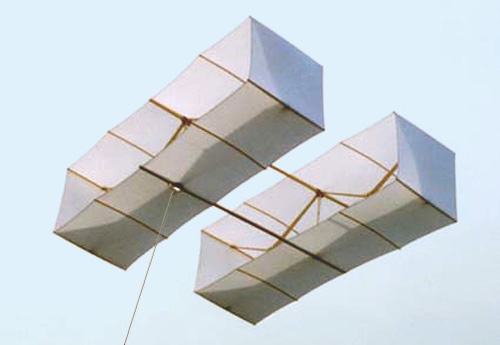
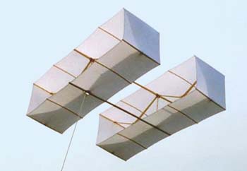 in flight... a larger copy of this image may be downloaded
On the initiative of Focaccia Fausto, Andrea Casalboni started kiting in Villanova di Bagnacavallo, Ravenna, Italy during the summer of 1989, as part of the "Gringo Loco Team" which focusses exclusively on aerial photography from kites, or 'KAP'. Fausto and Andrea are constantly researching and experimenting in order to improve their equipment and over the years, have tested many types of cameras and film and taken over 3000 photographs.
Andrea dedicates his 'spare' time to the construction of replica classic kites and camera cradles using photographs and drawings from the late 19th and early 20th century and is always happy to collaborate with other enthusiasts in this area and other related kiting activity.
Used with permission Send your comments on this page to the author Andrea Casalboni
|
 The Author