
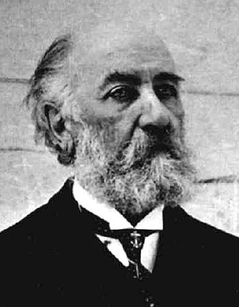
Victor Tatin (1843-1913)
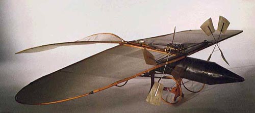
Frenchman, Victor Tatin became one of early aviation's most authoritative theorists. He built a model in 1879 with a fuselage that acted as a tank for the compressed air that drove a small engine linked to two tractor propellers. The model had a 75ins (1.9m) wingspan. It was attached to a pole, and flew in circles around the pole for some 49ft (15m). http://www.centennialofflight.gov
 Victor Tatin compressed air powered Aeroplane of 1879 Download a 750pixel image
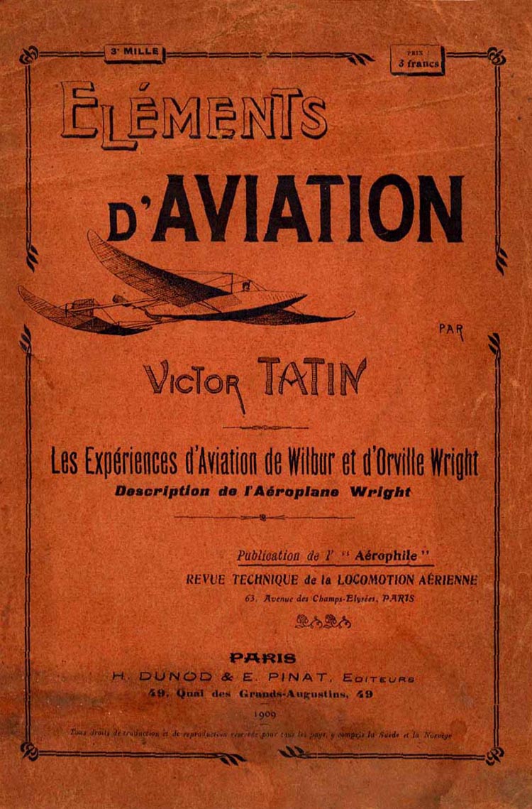
Progress in Flying Machines
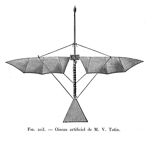 Victor Tatin Ornithopter of 1874 Download a 1000pixel image
This was driven by twisted rubber; not only did M. Tatin find that the power required was unduly great, but he also found that this power could not be accurately measured, the torsion of indict-rubber being erratic and stretching unequally.
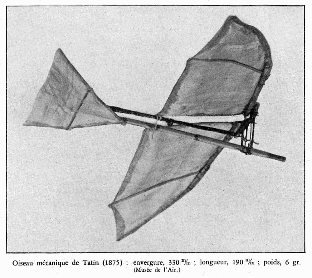
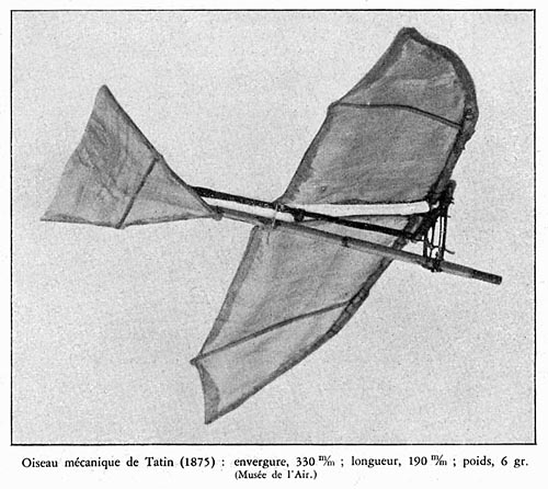 Victor Tatin Ornithopter of 1875 Download a 1000pixel image
He constructed a large number of mechanical birds of all sizes and various weights; he tried many modifications and entire or partial reconstructions, and finally concluded, after spending a good deal of time and money, to take up the aeroplane type, to be driven by a reservoir of compressed air. With this his efforts were successful almost from the first, and he produced in 1879 the apparatus shown in fig. 58, which is practically the first that has risen into the air by a preliminary run over the ground.
 Victor Tatin compressed air powered Aeroplane of 1879 Download a 1500pixel image
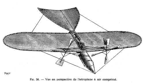
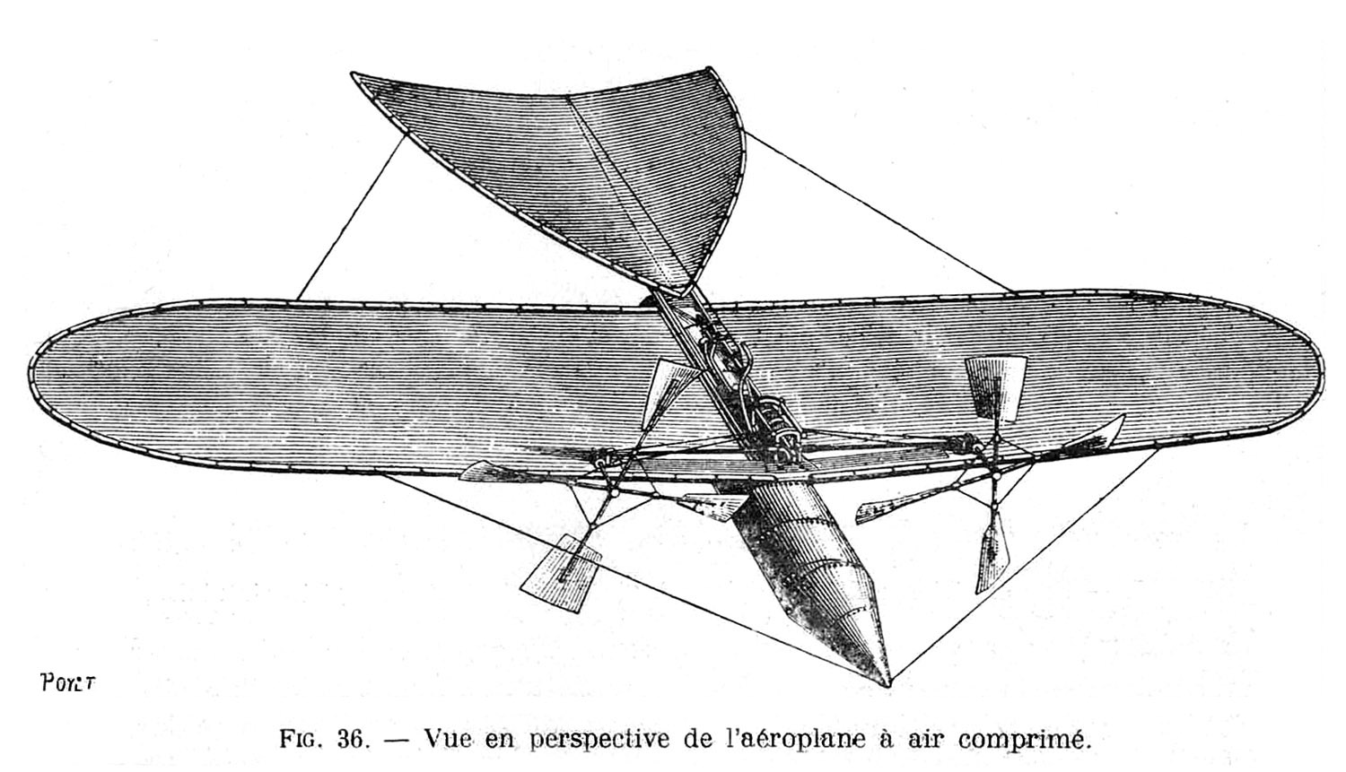
This machine consisted in a silk aeroplane, measuring 7.53 sq. ft. in surface, being 6.23 ft. across and 1.31 ft. wide, mounted in two halves at a very slight diedral angle, on top of a steel tube with conical ends which contained the compressed air. This reservoir was 4 3/4 in. in diameter and 33 1/2 in. long, was tested to a pressure of 20 atmospheres, and worked generally at 7 atmospheres; its weight was only 1.54 lbs., and its cubical capacity 0.28 cub. ft.
 Victor Tatin compressed air powered Aeroplane of 1879 Download a 1500pixel image
From this (the vital feature of the machine) the stored energy was utilized by a small engine, with oscillating cylinder, placed on a thin board on top of the tube, and connected by shafts and gearing to two propellers with four vanes each, located at the front of the aeroplane. These propellers were 1.31 ft. in diameter, and rotated in opposite directions some 25 turns per second, their velocity at the outer end being about 100 ft. per second. The vanes were of thin bent horn set at a pitch of about 1.50 ft., and they towed the apparatus forward instead of pushing it. A tail of silk fabric 1.97 ft. across at the rear, by a length of 1.97 ft., was set at a slight upward angle and braced by wire stays, in order to provide for the longitudinal stability upon the principle advanced by Pénaud and the whole apparatus was placed on a light running gear consisting first of four wheels, and subsequently of three wheels. The total weight was 3.85 lbs., so that the sustaining surface of the aeroplane (omitting the tail) was at the rate of 1.95 sq. ft. to the pound.
 Victor Tatin's aeroplane of 1879 http://invention.psychology.msstate.edu
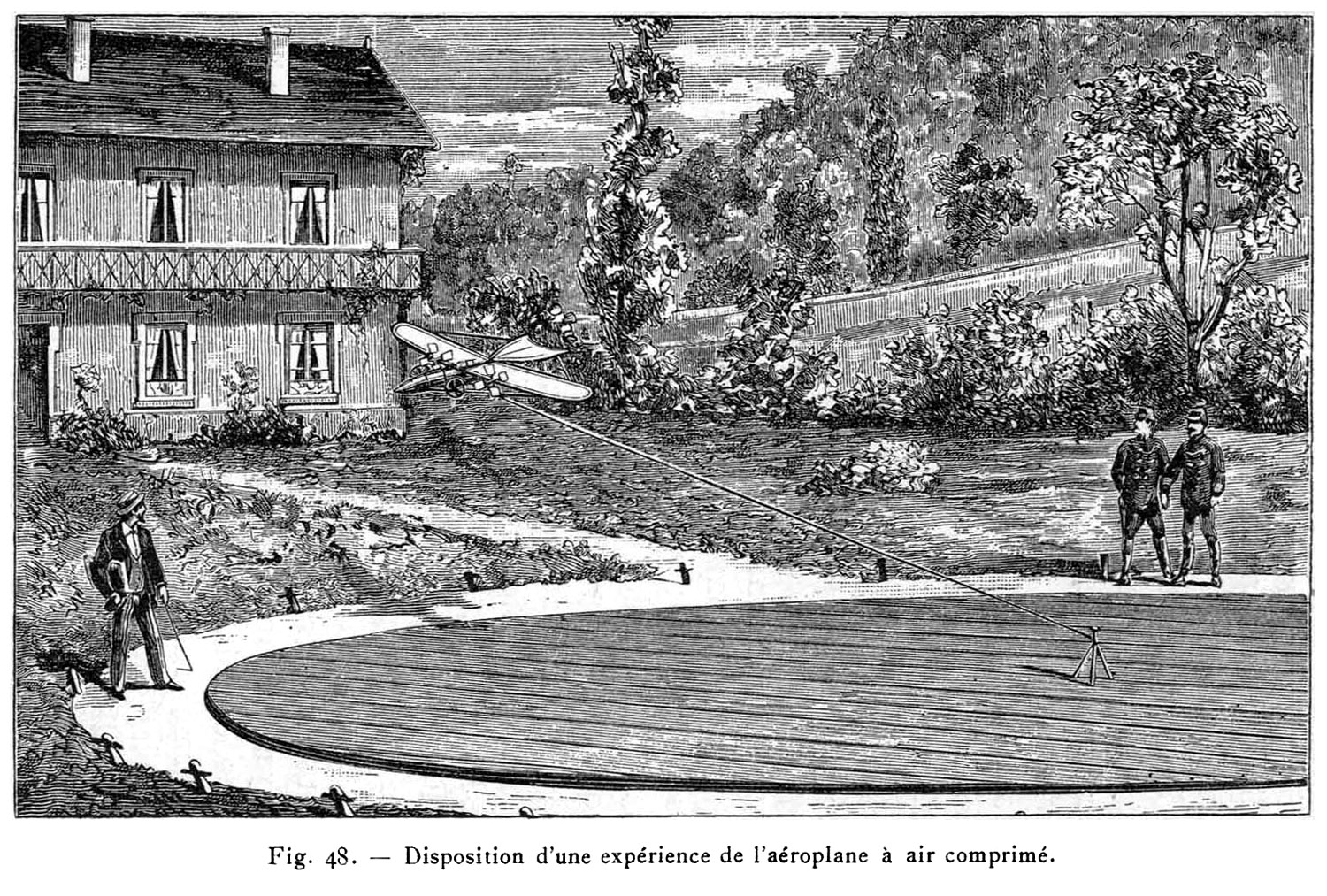
After a vast deal of preliminary testing and adjustment, the apparatus was taken to the French military establishment at Chalais-Meudon, where it was experimented with in 1879 upon a round board platform 46 it. in diameter. Upon this the machine would be set upon its wheels, the front and rear ends being fastened to two light cords carried to a ring around a central stake, and the compressed air would be turned on to the engine. The propellers would put the apparatus in motion and it would run from 65 to 165 ft. over the boards, until it attained a velocity of 18 miles per hour, when it would rise into the air, still confined radially by the two cords, and make a flight of about 50 ft., when, the power being exhausted, it would fall to the ground, almost invariably injuring the running gear in doing so. The flights were not very high, but on one occasion the apparatus passed over the head of a spectator. The angle of incidence was 70 or 8 o, and the power developed by the engine was at the rate of 72 33 foot-pounds per second, gross; but as its efficiency was only 25 to 30 per cent, of the gross power, the effective force was at the rate of 18.08 to 21.70 foot-pounds per second, or, say, at the rate of 5 footpounds per second (300 foot-pounds per minute) per pound of apparatus. This power was measured with great care, the machine being provided with a tiny gauge and tested repeatedly with a dynamometer. M. Tatin calls attention to the fact that the minuteness of the engine greatly diminished its efficiency, and that with large machines it would be comparatively easy to obtain 85 per cent. of the gross power developed. He draws the conclusion that his apparatus demonstrates that 110 lbs. can be sustained and driven through the air by the exertion of 1 horse power--a most important conclusion, which will be further discussed hereafter. To return, however, to the experiments: they are described as follows by M. Tatin : ----- "I will pass without description a series of preliminary experiments which led me to modify certain details, until all conditions were favorable. I then had the satisfaction of seeing the apparatus start at increasing speed, and in a few seconds the carriage barely touches the ground; then it leaves it entirely at a speed of about 18 miles per hour, which agrees closely with the calculations. It describes over the ground a curve similar to those described by small models gliding freely, and when it comes down after its orbit, the shock as so violent as to injure the running gear. This accident recurred upon each experiment carried out under the same conditions; the carriage was soon destroyed, and even the propellers were injured, although they could be repaired. l then tried another experiment, which I had already attempted several times without success, in consequence of inadequate preparation. The apparatus, the running gear being removed, was suspended by two grooved wheels running freely over an iron telegraph wire 260 ft. long, stretched as rigidly as practicable. When the speed became sufficient, the apparatus rose, and then one of the propellers struck the iron wire; the front grooved wheel overtook the machine, and the propeller was destroyed. These accidents caused no repining, for they demonstrated that in all cases the apparatus had completely overcome the force of gravity. In order to continue the experiments I built a new carriage and new propellers, hoping to make them strong enough to stand the shocks during a new set of experiments, from which to deduce accurately the work done, The new running gear had but three wheels, these being larger and lighter than the old. The propellers, on the other hand, were made heavier) but modified so as to rotate more easily. Their vanes were made of a thin sheet of horn bent hot to the proper curvature. The inner two-fifths from the hub consisted of steel wire, this portion of a propeller requiring much force for rotation, and giving out but small effect toward propulsion; but the diameter and the pitch were the same as formerly. I was, unfortunately, unable to make all the experiments I desired with this repaired apparatus. I intended to study the results with various angles of incidence in the planes and various pitch of the propellers; then to study the important question as to the best proportion between the sustaining surface and the diameter of the propellers; and lastly the speed of translation which will best utilize the force expended. I was nevertheless enabled to deduce the following figures from my experiments. These figures are not absolutely exact, but sufficiently so to serve as a guide to others who may wish to engage in similar work. Calling A the sustaining surface in square meters (without the tail), and V the speed of translation in meters per second, then we may say: Lift = 0. kg. .045 A V2. And the motor will need to develop effective work at the rate of 1.50 kilogrammeters per kilogramme of the weight (4.935 foot-pounds per second per pound), which corresponds to one horse power for each 110 lbs. weight of the apparatus. These experiments seem to demonstrate that there is no impossibility in the construction of large apparatus for aviation, and that perhaps even now such machines could be practically used in aerial navigation. Such practical experiments being necessarily very costly, I must, to my great regret, forego their undertaking, and I shall be satisfied if my own labors shall induce others to take up such an enterprise. ----- The effective work done by this aeroplane having been accurately measured, it affords a good opportunity of testing the method of estimating resistances which has been proposed by the writer in estimating the work done by a pigeon." The weight of M. Tatin's apparatus was 3.85 lbs. Its aeroplane surface was 7.53 sq. ft., the angle of incidence was 8 o, and the speed was 18 miles per hour, at which the air pressure would be 1.62 lbs. per sq. ft. Hence we have, by the table of "lift and drift": Lift, 8 o = 7.53 x 1.62 x 0.27 = 3.29 lbs., which indicates that a small part of the weight was sustained by the tail. The hull resistances are stated by M. Tatin to have been almost equal to that of the plane. These hull resistances would consist of that of the tube, of 0.12. sq. ft. midsection, which, having conical ends and parallel sides, will have a coefficient of about one-third of that of its midsection. The resistance of the wheels and running gear will be slightly greater, but must be guessed at, as the wheels would continue to revolve through inertia and thus increase the resistance. The front edge of the aeroplane, which was of split reed and about one-eighth of an inch thick, was 6.23 ft. long; but as the back edge of the aeroplane and the side borders of the tail would also produce some air resistance, we may call the edge resistance as equal to 6 ft. in length, by a thickness of 0.01 ft., without any coefficient for roundness. We then have the following estimate of resistances: Resistance of Tatin Aeroplane.
Drift 8 7.53 x 1.62 X 0.0381 = 0.4648 lbs. Power = 0.7268 x 26.4 = 19 19 foot-pounds per second, which agrees very closely with the 18.08 to 21.70 foot pounds per second said to have been effectively developed, and is at the rate of 5 foot-pounds per pound of apparatus, or of 110 lbs. of weight per horse power. This last is the important point. Now that Mr. Maxim has produced a steam-engine which, with its boilers, pumps, generators, condensers, and the weight of water in the complete circulation, weighs less than 10 lbs. to the horse power, aviation seems to be practically possible, if only the stability can be secured, and an adequate method of alighting be devised.
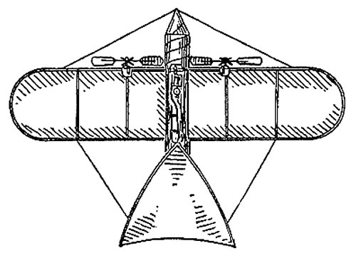
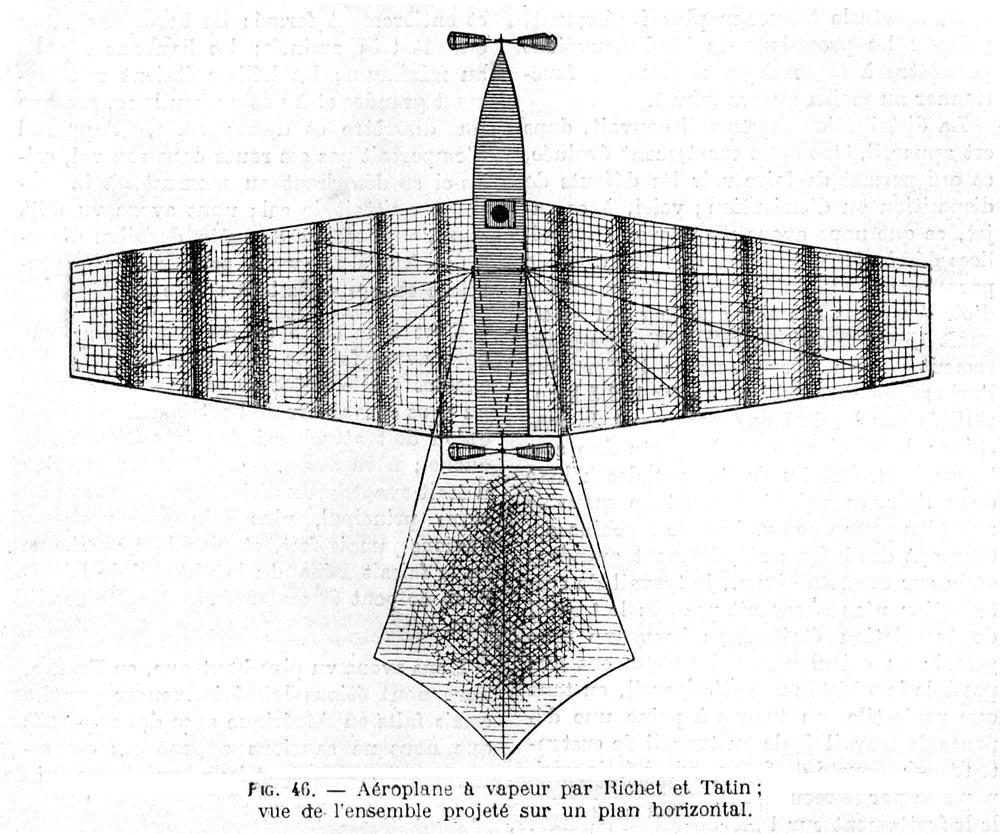
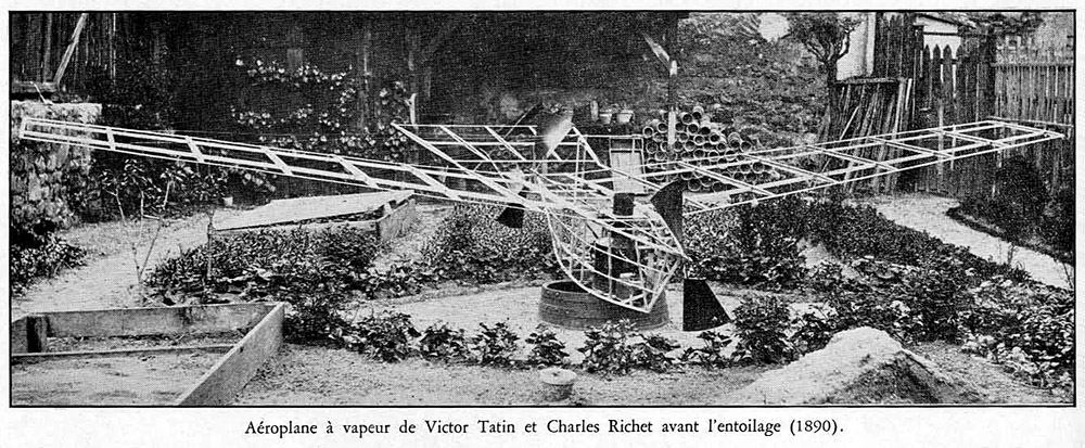
 Victor Tatin Steam Engine Aeroplane of 1890 Download a 750pixel image
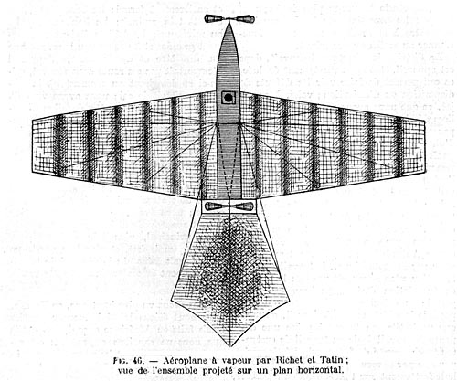 Victor Tatin Steam Engine Aeroplane of 1890 Download a 1000pixel image
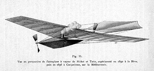
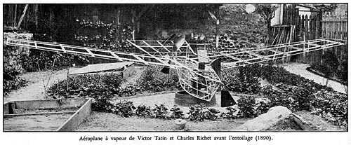 Victor Tatin and Charles Richet, 1890 Download a 1000pixel image
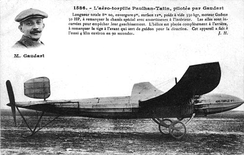
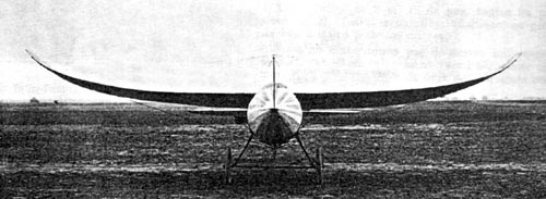
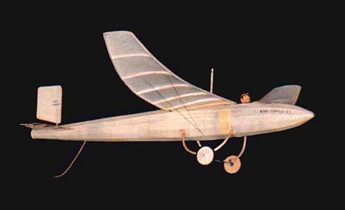
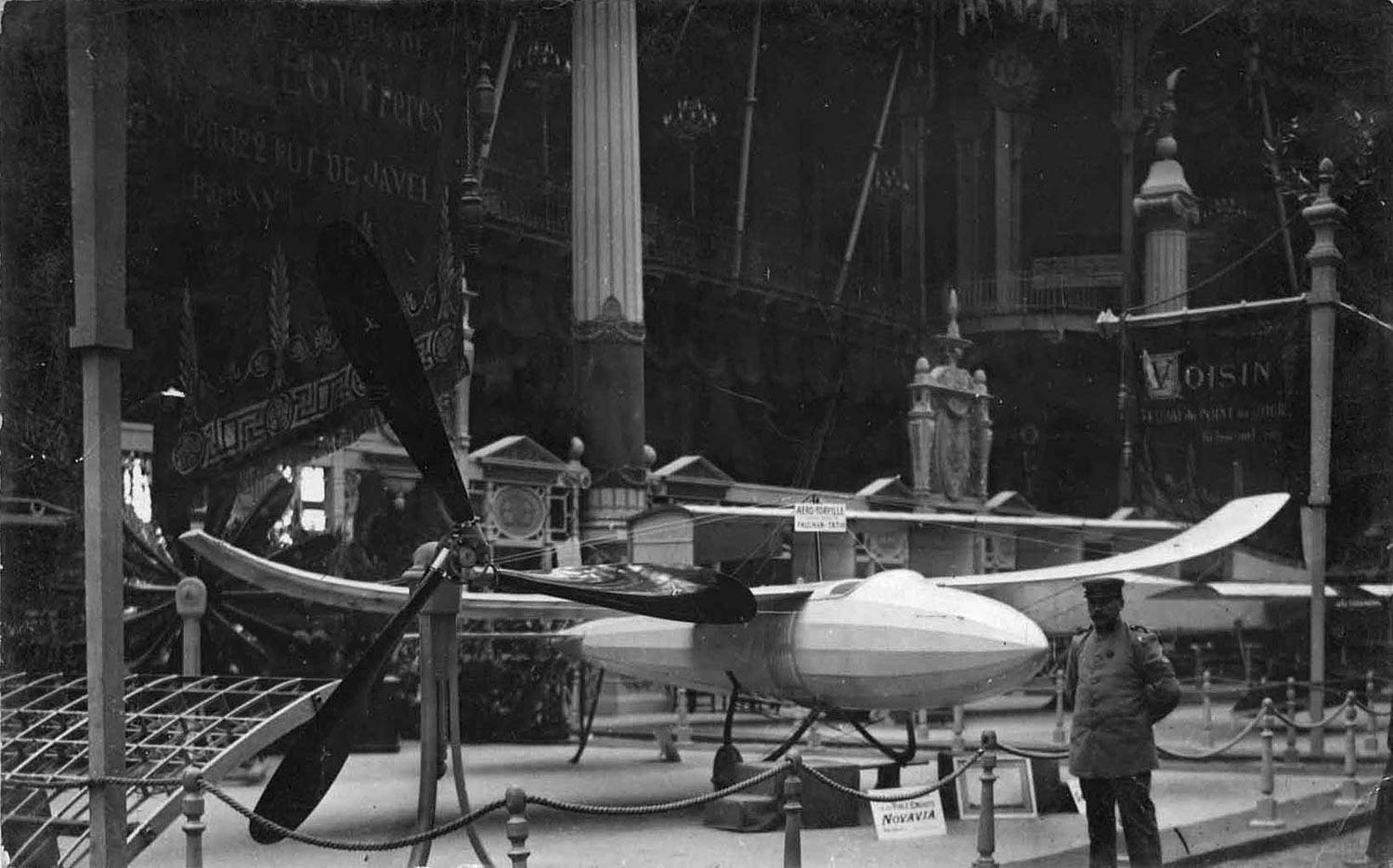
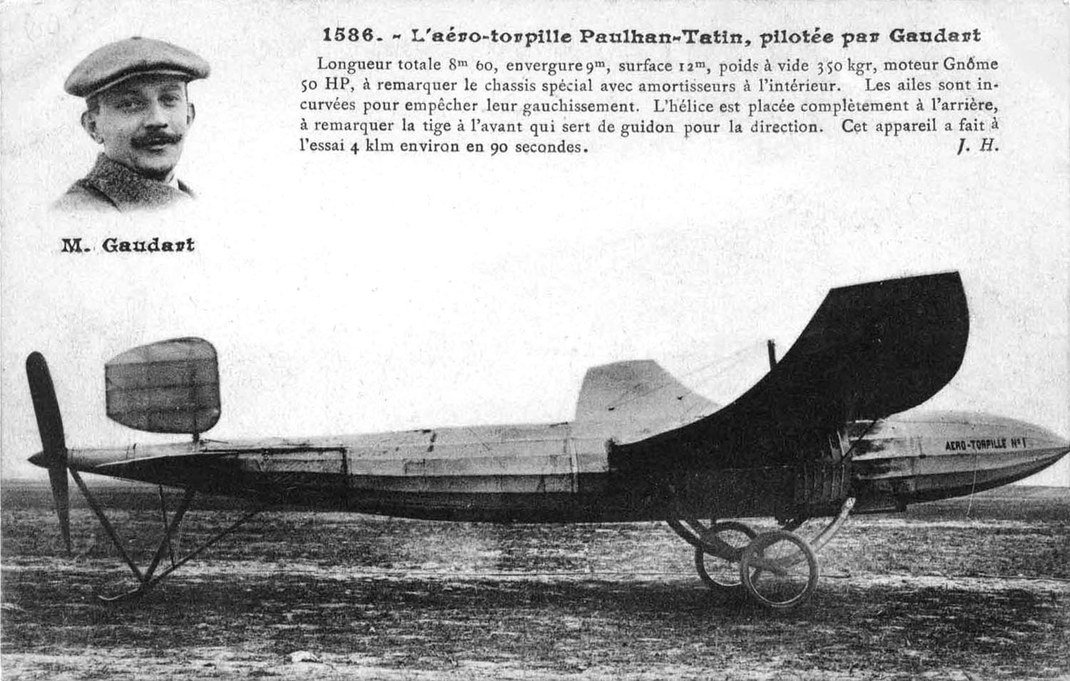
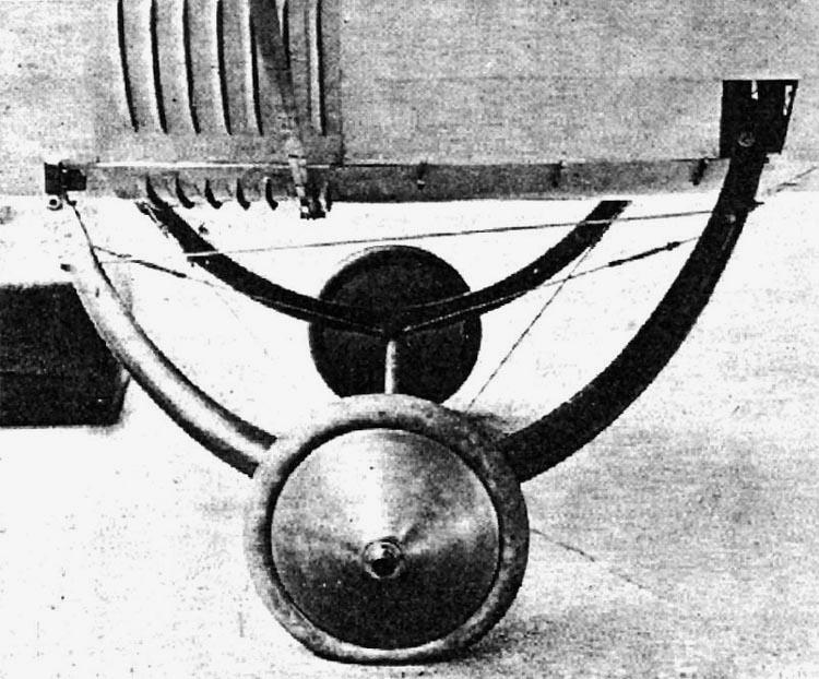
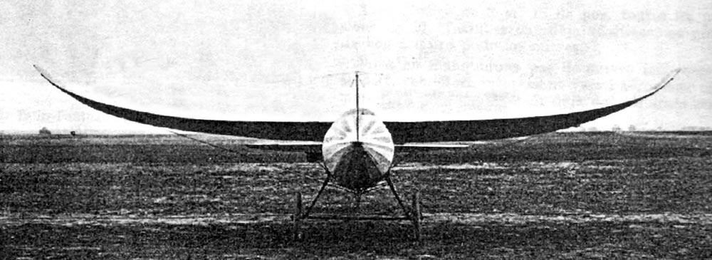
L'Aéro-Torpille 1911-1912 Tatin-Paulhan 1911 Tatin-Paulhan "Aero-Torpille" The Aero-Torpille sported artfully arched wings, a streamlined monocoque fuselage with a Gnome rotary engine buried within, its power delivered to a tail-mounted pusher propeller by a lengthy shaft.
 L'Aéro-Torpille 1911-1912 Tatin-Paulhan Download a 1500pixel image
 L'Aéro-Torpille 1911-1912 Tatin-Paulhan Download a 1500pixel image
 L'Aéro-Torpille 1911-1912 Tatin-Paulhan Download a 1500pixel image
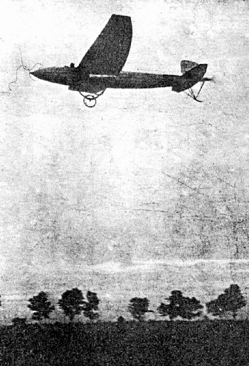
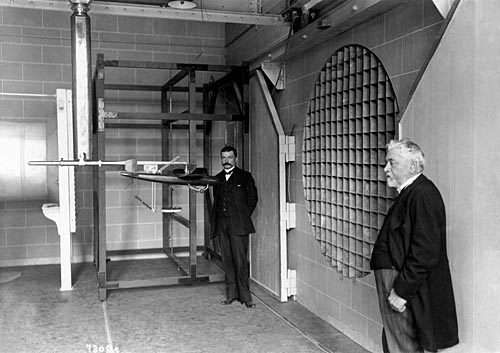 Testing a model of the Tatin-Paulhan 'Aéro-Torpille' Gustav Eiffel is at the right download a 1000pixel or 1500pixel image
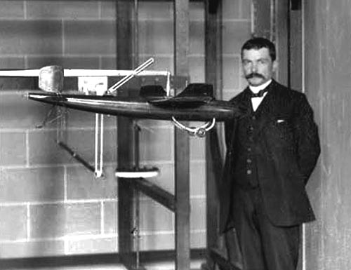 Testing a model of the Tatin-Paulhan 'Aéro-Torpille' (detail)
 L'Aéro-Torpille 1911-1912 Tatin-Paulhan Download a 500pixel image
 L'Aéro-Torpille 1911-1912 Tatin-Paulhan Download a 750pixel image
 L'Aéro-Torpille 1911-1912 Tatin-Paulhan Download a 1000pixel image
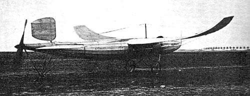 L'Aéro-Torpille 1911-1912 Tatin-Paulhan Download a 1500pixel image
RCM No. 2, Mai 1999 Le vol d'intérieur : une histoire ancienne ! par Christian Veyssière http://www.multimania.com
 L'Aéro-Torpille 1911-1912 Tatin-Paulhan
Le top model de l'aviation du début du siècle. Je ne vous ferais pas un historique de cet appareil, la rubrique PIONN'INDOOR s'en charge dans ce même numéro. Mais quand même, il est important de rendre hommage à nos ancêtres aviateurs.
"J'ai entendu déclarer par un des membres de notre Société que nous n'aurons jamais rien à apprendre des modèles. Ceci par quelqu'un qui est toujours prêt àconstruire un grand appareil, mais qui ne l'a pas encore commencé !"
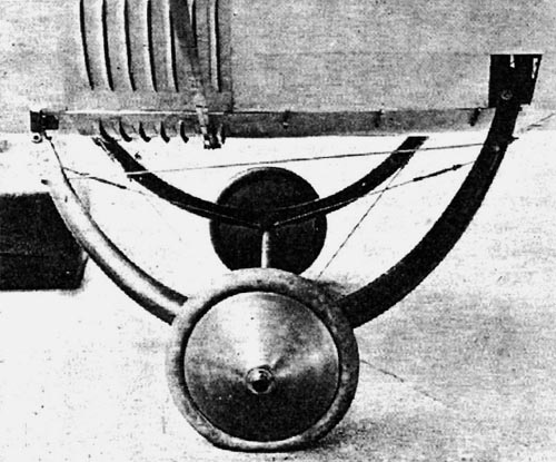
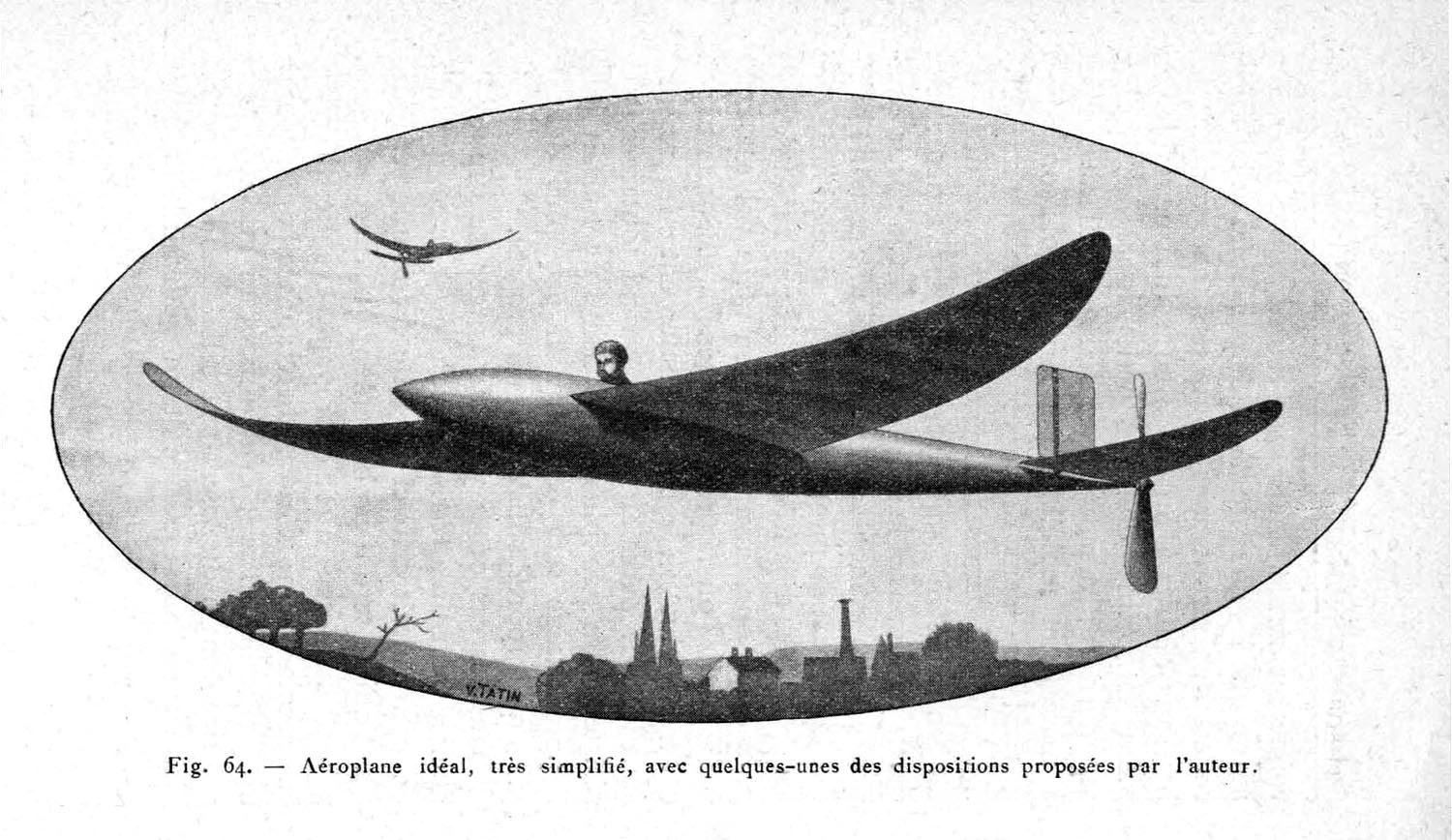
1879, un dénommé Tatin met au point un superbe avion à moteur à air comprimé volant en circulaire (quand je vous dis que l'on a rien inventé !) Ce chercheur et scientifique, en s'appuyant sur les travaux de Mouillard sur le vol plané des grands oiseaux, effectue des relevés sur les profils et les formes des ailes d'oiseaux. Sur ces données hautement scientifiques, vont naître une succession de projets dont les formes qui semblent hors du temps, offrent de superbes compromis de performance au vue de ce que certains bricoleurs s'acharnent à faire. En effet c'est avec une puissance réduite de 50 cv que Victor Tatin met son dernier appareil en vol. Son pilote Paulhan, qui est un des grands de l'époque, va démontrer que les recherches scientifiques qui prévalent à la mise au point de l'appareil sont les bases permettant à l'aviation d'avancer. Avec des vols dont la vitesse atteint 140 km/h, cet appareil démontrait ses qualités pour l'époque. Malheureusement les problèmes de refroidissement d'un moteur caréné et les problèmes de transmission (arbre long sans cardans) feront que cette appareil n'auras pas de suite. L'histoire nous montre qu'il ne suffit pas d'avoir raison pour être écouté !. Ce dernier appareil, portant le doux nom d'aéro torpille, vue sa forme, représente le condensé des connaissances aéronautique du moment. L'amélioration de la traînée par un carénage aérodynamique de l'ensemble des éléments embarqués, un profil d'aile donnant une stabilité naturelle, un système propulsif permettant d'obtenir le rendement optimal de l'hélice. En un mot une machine insolite et belle à la fois. Volera, volera pas, aussi bien roulée elle ne devrait pas avoir de soucis pour s `envoyer en l'air. Il serait dommage qu'elle finisse en "potiche" La torpille avec de nombreux vols ne restera qu'un instrument de recherche. On peut d'ailleurs voir les évolutions de structure au cours de la mise au point. Le train notamment a reculé entre la version exposé au salon de l'aviation et le modèle visible sur les recueils de photos du Musée de l'air
Further Reading
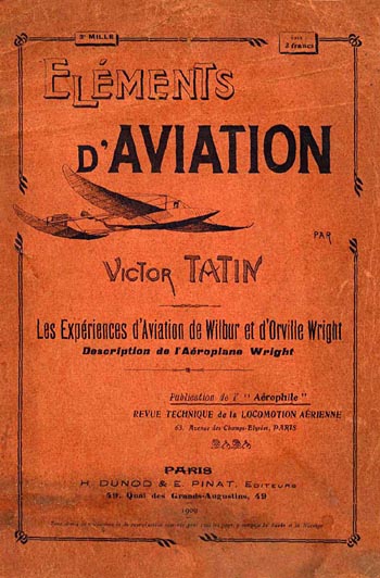 Victor Tatin Download a 750pixel image
 Victor Tatin Biography Download a 1000pixel image
|
 We next come to a series of very careful experiments, tried by an able mechanician, which almost demonstrate that artificial flight is accessible to man, with motors that have been developed within the last two years. These experiments were carried on by M. V. Tatin, who was then Professor Marey's mechanical assistant.
© Copyright 1999-2002 CTIE - All Rights Reserved - Caution |