
Horatio F. Phillips, (1845-1926)
Horatio F. Phillips Horatio F. Phillips, of England, began experimenting with lifting curved surfaces in the 1880's. In 1893, he constructed a large device for testing the effective lift of what he termed "sustainers" (airfoils). The "Phillips Flying Machine," as it was known, was 9-1/2 feet tall and about 22 feet long, with 40 lifting surfaces. It was mounted on a circular track 200 feet in diameter.
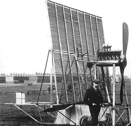
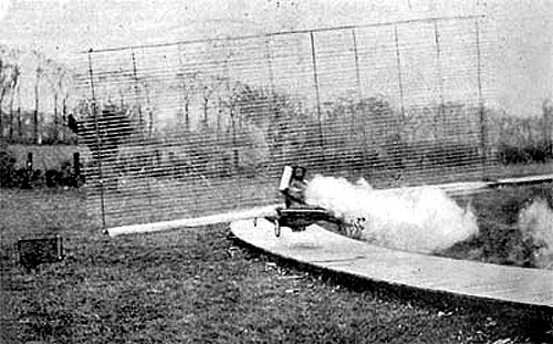 The Phillips Flying Machine For Testing Aerocurves, Harrow, England - 1893
A two-bladed propeller driven by a steam engine pulled the machine around the track. The Phillips Flying Machine of 1893 was able to lift its own weight plus 72 pounds (a total of 402 pounds) some three feet, at a speed of about 40 m.p.h.
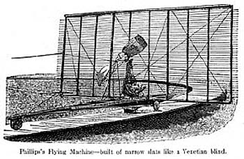
 Phillips Flying Machines as reported in American Engineer 1892/93
Phillips continued to experiment with wing designs, and built another flying machine test rig in 1902, which had 120 wings and was powered by a gasoline engine.
 The Phillips Flying Machine For Testing Aerocurves, Harrow, England - 1893 40 narrow wings, 40mph steam engine
Phillips built his first human-carrying machine, with 20 lifting surfaces, in 1904, and was able to make at least one short hop of 50 feet. His 1907 machine had four banks of 50 wings each and an 8 foot propeller. It was in this machine that Phillips made a powered, although uncontrolled, flight of about 500 feet.
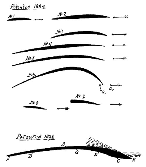 Phillips Patented Aerocurves - 1884 and 1891 http://invention.psychology.msstate.edu
As a result of his experiments, Phillips was able to prove his hypothesis that in a curved wing, where the curvature is greater on the top surface than the bottom surface, the lift is generated primarily by the upper surface. This proof had eluded Sir George Cayley, although he suspected it to be true. Phillips was a pioneer of aerial engineering who took up where Cayley left off, and began the systematic evaluation of curved surfaces meant for aerial machines.
Horatio F. Phillips An Englishman, Horatio F. Phillips demonstrated Cayley's theories of lift. In 1884, he patented eight wing-like sections of various widths and curvatures. He used a "wind box" to determine how fast an oncoming stream of air should be to sustain each different form carrying the same weight. His experiments proved that a curved surface creates more lift than a flat surface. In 1891, Phillips devised and patented an improved wing section designed to create even more lift. He explained that low pressure is produced on the blade's upper surface, while high pressure is produced on the underside. Since high pressure always moves toward low pressure, the high pressure below pushes the blade upward to the low pressure and creates lift. In 1893, he created a 350-pound (158.8-kilogram) model aircraft that ran around a 628-foot (181.4-meter) circular track attached to a central pole. The model rose about three feet (91 centimeters) off the ground when it reached a speed of 40 miles per hour (64 kilometers per hour). This model had fifty rows of superimposed small winglets arranged in a slat-like fashion on wheels. Each slat was twenty-two feet (6.7 meters) long and 1.5 inches (3.8 centimeters) wide and was mounted two inches from the next slat. A coal-fired engine turned a twin-bladed propeller 400 revolutions per minute. and also from http://www.centennialofflight.gov/ Horatio Phillips was born in 1845 in Streatham, a suburb of London, England. He was the son of a gunsmith. Little has been written about his education, but he demonstrated interest in aeronautics at an early age and he closely followed the wind tunnel and whirling arm research conducted under the auspices of the Aeronautical Society. His main contribution was in airfoil design. In 1884 and again in 1891, he tested a variety of airfoil sections in an early wind tunnel that used a steam injector to suck air in through the entrance of the tunnel. The steam produced an airflow through the test section that was of better quality than earlier wind tunnels had produced. Phillips' experiments demonstrated that on a thick cambered wing or airfoil section that was curved more on the top surface than on the bottom, the difference in pressure above and below the airfoil (pressure was less above the wing) produced lift. In 1884, Phillips received a patent for his two-surface wing sections. He received a second patent in 1891. His later experiments were less noteworthy although certainly dramatic. In 1893, he designed a flying machine with 50 wings to demonstrate his theories in actual use. His "multiplane" resembled a giant venetian blind. The frame measured 22 feet long and only 1.5 inches wide. A coal-fired engine powered the machine and turned the propeller. He tested his craft on a circular track and managed to rise some two-to-three feet off the ground when the engine ran at 40 miles per hour. He built another similar machine that ran on a larger track. In 1904 and again in 1907, he built conducted additional tests. His 1904 model had 20 wings and managed a shop "hop" of about 50 feet. His 1907 model flew about 500 feet.
A History of Aeronautics
XIII. First Flyers in England Certain experiments made in England by Mr Phillips seem to have come near robbing the Wright Brothers of the honour of the first flight; notes made by Colonel J. D. Fullerton on the Phillips flying machine show that in 1893 the first machine was built with a length of 25 feet, breadth of 22 feet, and height of 11 feet, the total weight, including a 72 lb. load, being 420 lbs. The machine was fitted with some fifty wood slats, in place of the single supporting surface of the monoplane or two superposed surfaces of the biplane, these slats being fixed in a steel frame so that the whole machine rather resembled a Venetian blind. A steam engine giving about 9 horse-power provided the motive power for the six-foot diameter propeller which drove the machine. As it was not possible to put a passenger in control as pilot, the machine was attached to a central post by wire guys and run round a circle 100 feet in diameter, the track consisting of wooden planking 4 feet wide. Pressure of air under the slats caused the machine to rise some two or three feet above the track when sufficient velocity had been attained, and the best trials were made on June 19th 1893, when at a speed of 40 miles an hour, with a total load of 385 lbs., all the wheels were off the ground for a distance of 2,000 feet. In 1904 a full-sized machine was constructed by Mr Phillips, with a total weight, including that of the pilot, of 600 lbs. The machine was designed to lift when it had attained a velocity of 50 feet per second, the motor fitted giving 22 horse-power. On trial, however, the longitudinal equilibrium was found to be defective, and a further design was got out, the third machine being completed in 1907. In this the wood slats were held in four parallel container frames, the weight of the machine, excluding the pilot, being 500 lbs. A motor similar to that used in the 1904 machine was fitted, and the machine was designed to lift at a velocity of about 30 miles an hour, a seven-foot propeller doing the driving. Mr Phillips tried out this machine in a field about 400 yards across.
'The machine was started close to the hedge, and rose from the ground when about 200 yards had been covered. When the machine touched the ground again, about which there could be no doubt, owing to the terrific jolting, it did not run many yards. When it came to rest I was about ten yards from the boundary. Of course, I stopped the engine before I commenced to descend.'
Flying Machines: Construction and Operation
Chapter I. Evolution of Two Surface Flying Machine : Renard's "Dirigible Parachute" I am asked to set forth the development of the "two-surface" type of flying machine which is now used with modifications by Wright Brothers, Farman, Delagrange, Herring and others. This type originated with Mr. F. H. Wenham, who patented it in England in 1866 (No. 1571), taking out provisional papers only. In the abridgment of British patent Aeronautical Specifications (1893) it is described as follows:
Two or more aeroplanes are arranged one above the other, and support a framework or car containing the motive power. The aeroplanes are made of silk or canvas stretched on a frame by wooden rods or steel ribs. When manual power is employed the body is placed horizontally, and oars or propellers are actuated by the arms or legs. A start may be obtained by lowering the legs and running down hill or the machine may be started from a moving carriage. One or more screw propellers may be applied for propelling when steam power is employed.On June 27, 1866, Mr. Wenham read before the "Aeronautical Society of Great Britain," then recently organized, the ablest paper ever presented to that society, and thereby breathed into it a spirit which has continued to this day. In this paper he described his observations of birds, discussed the laws governing flight as to the surfaces and power required both with wings and screws, and he then gave an account of his own experiments with models and with aeroplanes of sufficient size to carry the weight of a man. ...and as it applies to Horatio Phillips... [Ed] Phillips Fails on Stability Problem In 1893 Mr. Horatio Phillips, of England, after some very interesting experiments with various wing sections, from which he deduced conclusions as to the shape of maximum lift, tested an apparatus resembling a Venetian blind which consisted of fifty wooden slats of peculiar shape, 22 feet long, one and a half inches wide, and two inches apart, set in ten vertical upright boards. All this was carried upon a body provided with three wheels. It weighed 420 pounds and was driven at 40 miles an hour on a wooden sidewalk by a steam engine of nine horsepower which actuated a two-bladed screw. The lift was satisfactory, being perhaps 70 pounds per horsepower, but the equilibrium was quite bad and the experiments were discontinued. They were taken up again in 1904 with a similar apparatus large enough to carry a passenger, but the longitudinal equilibrium was found to be defective. Then in 1907 a new machine was tested, in which four sets of frames, carrying similar sets of slat "sustainers" were inserted, and with this arrangement the longitudinal stability was found to be very satisfactory. The whole apparatus, with the operator, weighed 650 pounds. It flew about 200 yards when driven by a motor of 20 to 22 h.p. at 30 miles an hour, thus exhibiting a lift of about 32 pounds per h.p., while it will be remembered that the aeroplane of Wright Brothers exhibits a lifting capacity of 50 pounds to the h.p.
The World's First Lifting Body In 1884 and again in 1891, British inventor Horatio Phillips tested a variety of wing sections in an early wind tunnel, in which he used steam to study the movement of air along various surfaces. He wrote:
"The particles of air struck by the convex upper surface...are deflected upward...thereby causing a partial vacuum over the greater portion of the upper surface,"And thus Phillips happened on to the principle behind every successful wing: air flowing over the curved top surface moves faster - and thus has lower pressure - than air flowing against a wing's flat bottom. It's the difference in pressure that produces lift. Had he left it at that, Phillips would have been remembered as having made a great contribution to aeronautical science. But he insisted on trying to build a flying machine. In 1893, he designed a craft with 50 slats (hence the name "multiplane"). Presumably, he was hoping all those planes would produce lift in abundance. The frame measured 22 feet long and only 1.5 inches wide; the machine was powered by a coal-fired engine that turned the propeller at 400 revolutions per minute. The whole thing looked like a flying Venetian blind. In 1892, Phillips managed to get the multiplane aloft for part of a lap over a circular track. That wasn't enough to impress fellow aeronaut and designer Octave Chanute, who wrote in his 1894 classic Progress in Flying Machines:
"Mr. Phillips experimental machine neglects any provisions for maintaining equilibrium in flight, or for arising and alighting safely."A 1907 design, which bore four frames with 200 tiny planes, flew some 500 feet; no word on how the version shown above, a 1911 single-frame machine, performed. Probably not impressively; the Venetian-blind airfoil is not one that designers have returned to often in the years since. It would be unfair to say this machine and others of similar design of that era were losers. Some actually flew and did so before the Wright brothers ` Flyer. A few even made tentative steps toward control. While the Wrights were-well-right, their machine was a sober pretty affair. The designs of the pre-Wright era have a boldness and extravagance that make them easy to like and root for, however futilely. And maybe that's instructive in its own right.
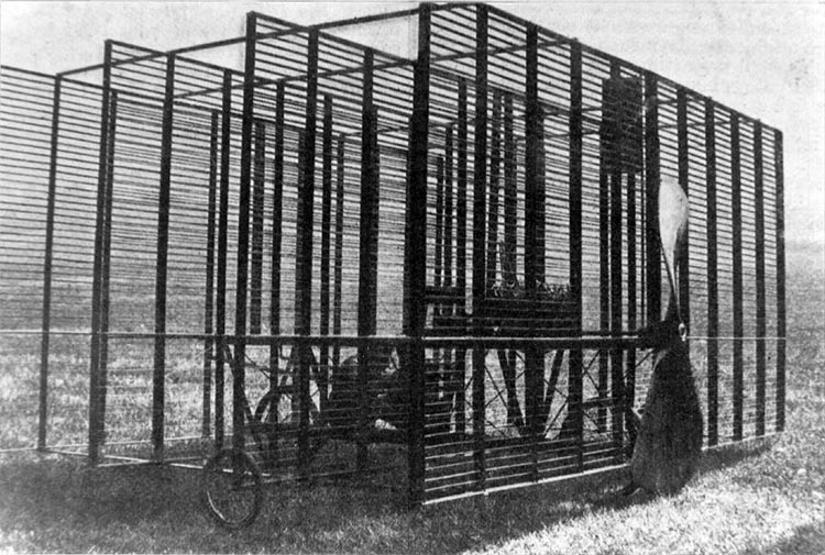
MultiPlanes Multiplanes include biplanes such as the Wright 1902 glider. Although the Wright brothers exploited the structural advantages of biplanes, rather than the lower vortex drag for fixed span and lift, their motivation was partly aerodynamic. Based on their own tests and those of Otto Lilienthal, it was apparent that at very low Reynolds numbers (typical of test conditions used by these pioneers) highly cambered, thin sections performed much better than thicker sections, making the cable-braced Lilienthal designs or the Wright biplane concepts especially attractive. Because of the low flight speeds required for Lilienthal's take-offs and landings and for the power plants available to the Wrights, the designs needed to be light and incorporate large wing areas. This requirement was satisfied well with the biplane configuration. The multiplane concept was taken to extremes by Phillips in 1904. The aircraft shown below with 20 wings would have had a high span efficiency, but the very low Reynolds number of each wing would lead to poor performance. The struts and cables of early biplane designs also led to large parasite drag, so the effects of improved span efficiency were not obvious. Several modern proposals for cantilevered or semi-cantilevered biplanes have emphasized the lower vortex drag of such configurations at the expense of structural efficiency, Reynolds number, and fuel volume. The induced drag of a multiplane may be lower than that of a monoplane of equal span and total lift because the nonplanar system can influence a larger mass of air, imparting to this air mass a lower average velocity change, and therefore less energy and drag. For a biplane, if the two wings are separated vertically by a very large distance, each wing carries half of the total lift, so the induced drag of each wing is 1/4 that of the single wing. The inviscid drag of the system is then half that of the monoplane. In addition to the well-known advantages in vortex drag, the favorable interference between two wings of a closely-coupled biplane can be used to improve the section performance. The lower-than-freestream velocity at the trailing edge of the forward wing and the new boundary layer on the downstream wing can be exploited and some of the difficulties with lower Reynolds numbers for the biplane as compared with a monoplane can be alleviated if not turned to advantage. Gains in CLmax, width of laminar drag bucket, and drag divergence Mach number at fixed t/c are possible with good multiple element section design. As an example, a single fully-laminar section (100% laminar flow on upper and lower surfaces) can support a CL of about 0.4. A 2-element wing can be designed with an overall CL of about 0.75. This may help to explain the preference for biplanes in the low Reynolds number world of insects.
Progress in Flying Machines Flight is possible with flat planes, as witness the butterfly, the dragon fly, and insects generally, but such creatures are endowed with greater relative power, as already explained; and, moreover, the elasticity of their wings produces change of shape under action. In the case of the birds, although the outer ends of the feathers are elastic, yet the wing is stiffer as a whole, and the curved surfaces may prove more efficient than planes in obtaining support from the air. this view seems to have prevailed with Mr. H. F. Phillips, for he patented, in 1884 a whole series of curved shapes, intended to be used in conjunction with suitable propelling apparatus for raising and supporting an aerial machine in the air. These shapes were to be utilized in a set of narrow blades arranged at suitable distances apart; the idea being to defect upward the current of air coming into contact with their forward edges when under motion, so as to cause a partial vacuum over a portion of the upper surface of the blade, and thus to increase the supporting effect of the air pressure below the blade. These shapes were the result of a series of experiments tried by Mr. Phillips in artificial currents of air, produced by induction from a steam jet in a wooden trunk or conduit, and described in London Engineering in its issue of August 14, 1885.
A cross-section of the shapes patented will be found on fig. 65 Nos. 1-8. The following table gives the results observed, the last column having been added by myself:
The intent of these experiments seems to have been to ascertain the speed of current required to sustain various forms and areas of surfaces, carrying the same weight in a soaring attitude. For this purpose they were exposed to the varying current with their long edges transversely thereto, and they were loaded with a weight applied one third of the width back from the forward edge, which point was thought to be the center of pressure. These shapes were swung by two wires attached to their front edges, and when they assumed a soaring attitude in the velocity of current required to sustain the weight, the "thrust" or drift was then measured.
Phillips patented aerocurves - 1884 and 1891 http://invention.psychology.msstate.edu
The most efficient shape is, of course, that which requires the least expenditure of power, or the smallest number of foot-pounds per pound of weight to keep it afloat and this is seen to be shape No 5, which soared with 3.77 foot-pounds per pound, or at the rate of 146 lbs. sustained per horse power, while the flat plane absorbed more than twice as much power. The comparison would have been more satisfactory if the soaring angles of incidence had been stated. This is given for the plane only as having been 15°ree; by measurement. This agrees fairly well with calculation; for if the "thrust" is to the "lift" as the tangent of the angle of incidence, then we have 2/9 = 0.222 = tang. 12°ree; 32'. But all the results obtained were probably somewhat vitiated by assuming that the center of pressure was uniformly one-third of the distance back from the front edge, and therefore applying the load at that point. We have already seen that this center of pressure varies with the angle of incidence in accordance with JoOEssel's law, and the load should have been attached accordingly. If, for instance, the possible soaring angle were 4°ree;, we should have for the position of the center of pressure, back from the front edge, a distance of 0.2 + 0.3 sin 4°ree; = 0.22 per cent, So that it seems probable that if its load had been applied at 22 per cent. instead of 33 per cent. back from the front edge the flat plane would have soared at a flatter angle than 15°ree; and would have shown less "thrust," because the effect of placing the weight so far back was to tilt the plane unduly, and thus to increase both the angle of incidence and the thrust. It is not known whether JoOEssel's formula applies to curved surfaces; but be this as it may, it is reasonable to believe that it would be but little modified, so that perhaps the error in locating the center of pressure operated to the disadvantage of the curved forms nearly as much as to that of the plane. We may, therefore, accept the general statement that greater weights per horse power can be sustained in the air with concavo-convex surfaces than with flat planes; but it seems very desirable that further experiments should be made, for it is quite possible that, in consequence of the loading of the blades at a point differing from the center of pressure, the shapes patented by Mr. Phillips are not absolutely the most efficient forms. It will be interesting, in this connection, to note how these various shapes behaved. It was found that in order to get the maximum efficiency from any given surface, the greatest depth of hollow should be one-third of the total width from the forward leading edge, and that the amount of concavity of the lower surface and the convexity of the upper surface should bear a relation to the speed of the air current. Thus in shapes 1 and 2 the under surface was nearly flat, and the upper curvature not great, while speeds of current of 60 ft. and 48 ft. per second were required respectively to produce a soaring attitude. In shape 3 the curvature was more marked, and the required speed fell to 44 ft. per second. Shapes 4 and 5 were made broader, with a moderate degree of curvature both above and below, and the speeds of current to produce soaring were 44 ft. and 39 ft. per second respectively. Shape 6 was an extreme case, in which the distinguishing features of the experiments were purposely carried to excess; for when impinged upon by a current of air of 27 ft. per second in the direction of the arrow a0, it was seen (by a fine attached ribbon) that there was an induced current flowing outward in the direction a1, Shapes 7 and 8 were used to demonstrate that the impinging air is deflected upward by the forward part of the upper surface, and that a partial vacuum results in the after part; they were not loaded with weights, and when exposed to a current of air of sufficient velocity, coming in the direction of the arrow, they rose into the position shown in the figure, In 1890 Mr. Phillips patented an aerial vehicle in which these curved surfaces were applied to an apparatus similar to the "dirigible parachute" of Commandant Renard, except that there were to be two (or more) series of curved blades behind each other at suitable distances apart, They were to be attached to an elongated body, which he indicated might be of fish shape, and, say, 30 ft. long, The cross-blades, which he termed "sustainers," might be 15 ft. long, 6 in. wide, and 2 in, apart, so many being superposed as to furnish the required supporting air surface. Each set of "sustainers" was to be held in place by a number of vertical bars of angular form! so as to offer the least resistance to the air. The propelling power was not indicated specifically, save the general statement that it should be "suitable," but a rudder was located at the top of the front series of curved blades, being affixed to a spindle bar terminating below (at the body) with a lever arm. A shifting weight was also provided, capable of being moved across the body, transversely to its line of motion, in order, when moved to either side, not only to depress it, but, by the resistance of the air acting on the surface of that weight, to check forward motion on that side, and thus cause the machine to describe the curve required. The patent drawings show the vertical standards carrying the blades as being rigidly attached to the body instead of being pivoted thereto, as in the case of Commandant Renard's device, and hence the angle of incidence of the machine could not be conveniently varied in order to rise or to descend; but it is probable that Mr. Phillips has long since remedied this defect, for he is understood to have been continuously experimenting, although the results attained have not as yet been published.
He apparently concluded that he had not developed the best shape in 1884, for he patented, in 1891, the form shown at the bottom of fig. 65. In this, the upper side A of the blade was made convex, as formerly, but the after portion of the lower side of the blade was made concave, as shown at B, while the curvature of the forward portion of this lower side was in the form of a reverse curve consisting of a convex curve, C, at the forward edge, followed by a concave curve, D He states in his patent: "The particles of air struck by the convex upper surface 4 at the point E are deflected upward, as indicated by the dotted lines, thereby causing a partial vacuum over the greater portion of the upper surface. The particles of air under the point E follow the lower convex and concave surface C D until they arrive at about the point G, where they are brought to rest. From this point G the particles of air are gradually put into motion in a downward direction, the motion being an accelerating one until the after edge Fof the blade is passed. In this way a greater pressure than the atmospheric pressure is produced on the under surface of the blade."Mr. Phillips indicates that such blades may be of wood, 12 ft. in length and 6 in. in width, from the leading edge E to the rearward edge F, but further experiment led him to make these blades still narrower, and he finally constructed an experimental machine which was tested in the early part of 1893, and has been described in various English journals, notably in Engineering of March 10 and May 5, 1893 the latter issue containing four illustrations, which were reproduced in the AMERICAN ENGINEER for June, 1893. From these various publications the following description of the Phillips experimental machine is compiled. Instead of providing two series of curved blades, one behind the other, there was but one set, approximately as shown in fig. 64. The apparatus looks like a huge Venetian blind with the slats open. There are 50 of these slats or "sustainers" I 1/2 in. wide and 22 ft. long, fitted 2 in. apart in a frame 22 ft. broad and 9 1/2 ft. high. The sustainers have a combined area of 136 sq. ft.; they are Convex on the upper surface and concave below, the hollow being about 1/16 in. deep. The frame holding the sustainers is set up on a light canoe-shaped carriage, composed principally of two bent planks like the two top streaks of a whale boat, and being 25 ft. long and 18 in. wide, mounted on three wheels I ft. in diameter, one in front and two at the rear. This vehicle carries a small boiler with compound engine, which works a two-bladed aerial screw propeller revolving about 400 times per minute. The fuel used is Welsh coal. There is said to have been no attempt to provide exceptionally light machinery. The weights of the various parts of the machine are, approximately: carriage and wheels, 60 lbs.; machinery with water in boiler and fire on grate, 200 lbs.; sustainers, 70 lbs.; total weight, 330 lbs. The machine was run on a circular path of wood with a circumference of 628 ft. (zoo ft. diameter), and to keep it in position (preventing erratic flight) wires were carried from various parts of the machine to a central pole, as in the Tatin experiments heretofore described. Still further to control the flight, which there is no means of guiding, as the machine is not of sufficient size to carry a man, the forward wheel is so balanced that it never leaves the track, and therefore serves as a guide, carrying some 17 lbs. of the weight, the remainder being on the hind wheels. On the first run 72 lbs. dead weight were added, making the total lift 402 lbs. As soon as speed was got up, and when the machine faced the wind, the hind wheels rose some 2 or 3 ft. clear of the track, thus showing that the weight was carried by the air upon the Venetian blind sustainers. A second trial was made with the dead weight reduced to 16 lbs. and the circuit was made at a speed of about 28 miles per hour (2,464 ft. per minute), and with the wheels clear of the ground for about three-fourths of the distance That the machine can not only sustain itself, but an added weight, was demonstrated beyond all doubt, even under the disadvantages of proceeding in a circle, with the wind blowing pretty stiffly. It is stated in the journal Iron that the boiler is a cylindrical phosphor-bronze vessel 12 in. in diameter and 16 in. long. The fire grate area is 70 sq. in., and the fuel Welsh coal. The engine is compound, having cylinders 1 3/4 in. X 3 5/8 in. X 6 in. stroke, fitted with ordinary slide valves. The working pressure of steam is 180 lbs. per square inch, The propeller is 6 ft. in diameter and 8 ft. pitch, with a projected blade surface of 4 sq. ft. The machine was also moored by a stern rope in which a dynamometer was inserted, and on the engine being run at full speed the dead pull was 75 lbs. If the latter figures be correct, then the power developed was 75 X 2,464 ÷ 33,000 = 5.6 horse power, and the weight carried per horse power was 402 ÷ 5.6, or 72 lbs. per horse power, which is inferior to the 110 lbs. per horse power carried by M. Tatin's apparatus, and probably due to the increased resistance produced by the frame which holds the sustainers. Mr. Phillips's experimental machine neglects any provisions for maintaining equilibrium in full flight, or for rising and alighting safely. Those he may add later; but whether he does or not, he is entitled to great credit for having been among the first experimenters who have tested concavo-convex surfaces instead of adhering to plane surfaces, and who have thus drawn attention to what may prove to be a very important line of inquiry. Almost all scientific experiments in air have hitherto been tried with planes, and such few formula as have been proposed are based upon the effect on flat surfaces. It is probable that such formulae--those of Smeaton, Duchemin, Joessel and others-will be found to need modification, either in form or in constants, when applied to curved surfaces. In such case the tables of "lift" and "drift" heretofore given herein will either need recalculation for each specific curved shape, or require the application of a variable coefficient, as exemplified in the calculations of the power expended by the pigeon as heretofore given. In any case it seems very desirable that further scientific experiments be made on concavo-convex surfaces of varying shapes, for it is not impossible that the difference between success and failure of a proposed flying machine will depend upon the sustaining effect (with a given motor) between a plane surface and one properly curved to get a maximum of "lift."
Horatio Phillips and Cambered Wing Design Horatio Phillips advanced the discipline of applied aerodynamics with his wind tunnel experiments in the early 1880s. These experiments quantitatively demonstrated George Cayley's theories relating to cambered airfoils-that cambered airfoils produce more lift than flat airfoils. Phillips used the results of his experiments to build three flying machines that, although they had only limited success, applied his theory of lifting surfaces. Phillips used the results obtained in his wind tunnel experiments to design a series of cambered airfoils based on the shapes of birds' wings. He called these the "Phillips entry," or "blades for deflecting air." They had greater curvature on the top than on the bottom and were called "double-surface airfoils." In 1884, he obtained a patent for eight of these airfoil sections, which were of various widths and curvatures. The theory of lift that these wings demonstrated was based on the variation in camber between the upper and lower surfaces of the wing. If the curvature of the upper surface of a wing was greater than that of its under surface, according to this concept, the air would flow over the upper surface at a greater velocity and produce lower pressures than on the underside. Hence an upward force-lift-would be generated as the higher pressure under the surface sought to become equal with the lower-pressure air above the surface. ...more
Hélice de H. Phillips 1893 : Hélice de H. Phillips de 1,8 m de diamètre ayant servi à des expériences de mesure de portance d'une aile multiplane (40 lames). Entraînée par un moteur à vapeur de 6 ch, (à 400 tr/min et 12,5 kg de pression). Cette hélice aurait fourni une traction de 34 kg.
Fliegende Jalousie 1884 hatte der Engländer Horatio Phillips die Richtigkeit der aeronautischen Theorien bewiesen, die George Cayley 90 Jahre zuvor aufgestellt hatte; er baute für die Aeronautical Society einen Windkanal und leitete Dampf über ein Flügelsegment mit unterschiedlich gewölbter Ober- und Unterseite - einer Tragfläche. Er bewies, daß sich auf der Unterseite eines Flügels, wenn er oben stärker gewölbt ist als unten, ein erhöhter Luftdruck bildet, der in emporhob. Phillips Schriften sollten von grundlegender Bedeutung für die Luftfahrt werden, doch für seine eigenen praktischen Versuche wählte er einen Vieldecker, der mehr Ähnlichkeit mit einer Jalousie als mit jedem anderen Flugzeug hatte, das je gebaut wurde. 1907 flog die Maschine in Streatham, London, tatsächlich 150 Meter weit, und Phillips gelang damit der erste bemannte Motorflug Großbritanniens, obwohl er nie als solcher anerkannt wurde. Außerdem besaß dieser Flugzeug noch keine wirksame
The First True Aerofoils The first would-be aviator to approach the problem scientifically was Englishman Horatio Phillips. He virtually invented the science of aerodynamics. In 1884. he took out his first patent for a cambered wing and then tested dozens of different aerofoil sections. These were not just cambered sheets, but aerofoils (wings) that had a rounded leading-edge, were thicker in the middle, and had a sharp trailing-edge.
 Phillips Multiplane of 1904 20 wings and managed a short 'hop' of about 50ft Download a 750pixel image
 Phillips Multiplane of 1907 Four rows, each with 50 wings, and an 8ft propeller. Makes an uncontrolled, powered hop of 500ft - the first in England Download a 750pixel image
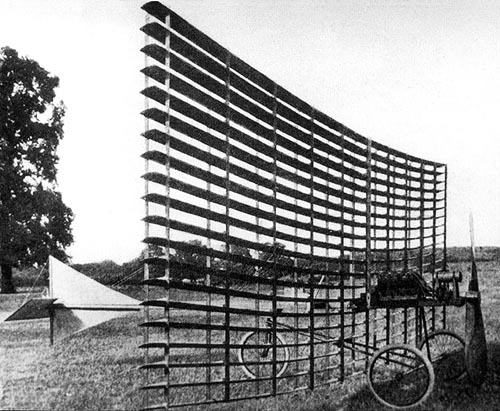
 Phillips Multiplane of 1911note Fitted with 110 narrow wings, it was powered by a 6 cylinder inline engine, which in turn drove a propeller that measured some 8 * ft or 2.6m Paul Dunlop NZ
Please Note : Mistakes of history are rife on the internet in this case the above machine is incorrectly stated to be a Phillips Multiplane of 1902 "with 120 wings, driven by a powerful petrol engine and capable of lifting 385 lbs in tethered flight".
|
© Copyright 1999-2004 CTIE - All Rights Reserved - Caution |