Lift Fans and How to make a Pressure Gauge
There are many ways of creating lift, some are better than others. I experimented along this paticular line because commercial fans did not perform sufficiently well.
Discussion with others who are interested in developing a better system has resulted in improvement over even this, our first pressure fan. Stay Tuned
Where I use the term 'aircon fan' it's because Multiwing and other manufacturers are clear that their fans are just that Air condition and air movement fans
Aircon blades in these fans are PAG Nylon either 4Z or 5Z type or equivalent.
Don't make the mistake of comparing hovercraft lift requirements with truck or bus radiator cooling requirements
Hovercraft lift depends entirely on the actual operational parameters and circumstances. For example: Racing craft are very light, requiring less presure than heavily loaded hovercraft.
Generally the pressure is between around 64mm Wg.
Why are the actual performance results are different from the manufacturer's simulator results when the fans are used in hovercraft. Because the fans are wind tunnel tested in ideal conditions, Hover craft plenums are far from ideal and require different testing.
These are my findings based on lift requirements for hovercraft in far from ideal circumstances and conditions.
The most common fans seem to be the Multiwing and Breezax brand of air conditioning fans. They are relatively inexpensive and they have been used in hovercraft for many years.
The Manufacturers will not recognise or apporove their use in hovercraft so it is a matter of 'enter at your own risk'. But they work.
Keep a close eye on the fan blades and the hub sections. The blades rub on the duct and wear. Sand and water deteriorate the blades, Cold hardens the blades. Cracked or damaged blades must be replaced and the fan re-balanced.
When I was into model aircraft, we used to boil the nylon prop blades for a few minutes in water to resoften them, this however would make PAG Nylon blades too soft for hovercraft use and is not recommended.
Remember that the fan is running at thousands of RPM so any out of balance will vibrate severely.
It takes a lot of wasted power to drive these fans because only the tips and about 40% in from the tips does any work, the remaining root half of the blade is quite useless for hovercraft, causing the air to swirl around and between the blade roots, this absorbs POWER like you wouldn't believe and gives nothing in return.
The optimum pitch for these blades is around 20 - 25 degrees near the tip because the blade, toward the root pitch increases to about 40 - 50 degrees, quite useless for hovercraft purposes.
I have tried Multiwing fans 6, 8, 9, 10 and 12 blades at pitches of 15, 20, 22.5, 25, 30 and 37.5 and achieved 64mm Wg (about 640Pa).
Using 15 deg pitch I got only 45 mm Wg (450Pa approx) The best effect was with 12 blades at 30 deg pitch which gave 64mm wg but no air escaped back through the blades when the craft fingers went over undulations or waves.
Calculating air requirements for an ideal static situation is unrepresentative, the craft performs exceptionally on solid smooth surfaces - like on a concrete floor in your shed - but on water, the escaping air forms a hollow at the skirt contact point and the craft flys closer to the surface, we get more spray and any bumps, undulations or waves distort the skirt allowing air to escape.
Allow to have more air than you think you will need.
My Story
First, I read the book on Axial Fan Design Principles, then had lengthy discussion with "The Man Who Wrote the Book" on axial Fans, Mr R.H Wallis, who suggested trying blade sections cut from PVC pipe as airfoil sections for testing purposes. The resulting blades ae cambered flat plate section but that way I could try various chords, tapers, hubs and number of blades.
I have done a lot of work on the design of lift fans (hundreds of hours plus) because there is/was little information available. There is no practical information relevant to hovercraft, but manufacturers have been designng and making these fans for many many years.
I started with the multiwing type of fan and progressed through about 20 different home made types of 4 to 24 blades. I used Marine ply for the hubs and then cut PVC pipe into certain shapes which gave me fairly good blades which I bolted onto the ply disc.
Believe it or not but the fans do not fly apart during testing on and off hover, in the shed but I would not use PVC 'Out There'.
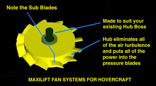
With hovercraft using aircon fans, the air pressure escapes back through and circulates around the centre of the fan because the hub outer diameter and hub area is too small, the blade roots have too much pitch and the blades are traveling too slow. You can check this by calculating the tip speed on full load hover, then calculate the root speed on full hover - now run the fan so the tips are travelling at the same speed as the previous root speed calculated - see if the hover craft lifts (it doesnt).
Calculation for tip speed:
Diameter x 3.142 x RPM = feet or metres per minute (divide by 60 to get Ft or Mtr per second)
Calculate for tips and root/hub diameter. You may find that the root travels at around half of the tip speed.
The maximum pressure from any fan is approximately average of the lowest pressure the fan generates at the blade root calculated by taking the root pressure, add this to the tip pressure and divide by 3.
Dont believe me? ---- make a pressure gauge as shown and check it yourself.
Check the pressure (suction) at the tips and at the root on the -Air in - side of the fan, it's substantially different.
Now check the pressure under the fan at the tips and root its about the same, (root pressure) not the tip pressure on the suction side.
Aircon blades swirl the air because of the very high pitch at the roots, are costly to drive, absorbing so much power from the lift engine and because they operate in very low pressure at the root, the higher air pressure generated by the tips and bounce back while travelling, blows back through the low pressure area causing the air to travel span wise, upsetting the pressure at the tips --- And So It Goes. ----
We have built deflectors under the fan and a filler cylinder to remove the dead area under the hub but the air still travels spanwise along the trailing edge of the blades.
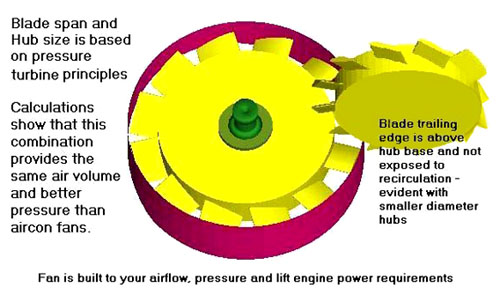
I found that the hub MUST fill much more than 1/2 area of the duct. Stub blades do all the work. The inside half of the blade is useless. The span of the blades is a percentage of the duct diameter and the chord is a percentage of the duct circumference. The airfoil section is important, I have found that a modification of the of Clarke 'Y' section works well because this section creates far less tendency to spanwise flows other sections (heavily undercambered) exacerbate spanwise flows when operating under high pressure circumstances. You can check flows by applying light oil and colored chalk dust to both the top and the under side of the blades then running then at hover speed for a few minutes. Basically, half of the chord (Blade width) at the root has full span flows and no or very little usefull lift character. For these reasons it seems that that the maximum pressure from commercial fans and hubs never exceeds 64 mm Wg or around 2.5 inches Wg in hovercraft applications. This is OK for most craft but leaves no reserve performance in commercial craft. Good lift pressure for load carrying should be 120 - 180 mm Wg or 6 to 8 inches Wg. Water Pressure Gauge For more information or plans on how to build your own pressure gauge which will very accurately check the actual skirt and lift pressure email hovergo SG Wg means Water gauge. See the hints and tips page under Air and Pressure for more information.
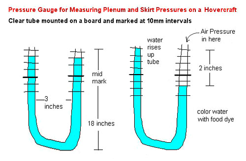
To make a water gauge or Manometer as per the sketch. Get a 2-3-metre (6 - 10 ft) length of 6-10mm (1/4 or 3/8 inch) clear plastic tube. Bend the tube to form a "U" shape about 200mm 8" long and 80 - 100 mm 3-4" wide and attach this to a plank of wood 4" wide with soft clamps. Draw 10 - 12 parallel lines 10 mm apart under the bent part of the hose pipe starting about 50 mm from the bottom of the bend. Mark the middle line as "0" and then 1,2,3,4,5 up and 1,2,3,4,5 down. With the wooden plank vertical now drip water into the pipe until the water is up to the middle line in both sides of the bend. Drop a few drips of green food colour into the water to make it more visible. You now have the "U" tube at one end and about 2.5 metres free at the other end. Do not block the tube ends but you can crimp the "U" end slightly to stop water from spilling. Both ends must remain open to the air. Make sure that the water levels are at the "O" mark by sliding the tube up or down slightly. With the hovercraft on a flat bench or concrete floor start the engine and put the other end of the clear tube under the skirts, the water will rise up the tube about 20- 35 mm, it will not blow all the water out of the tube. The actual pressure measured is the total pushed up the tube, about 25 - 30 mm PLUS the total pushed down the other side of the "U" tube, about 28 - 35mm. This will be around 60 - 65mm or 2-3 inches, this is the skirt pressure. If you load the hovercraft so that it will not hover, even on full pressure, you will find that the skirt pressure is approximately the same as with no load. This is because of the nature of a multiwing fan in a hovercraft duct, (Hub area.) There is quite a misunderstanding about these air fans, they have been used in hovercraft for many, many years and cannot be dramatically improved for the application. Hovercraft applications are the worst possible use for air conditioning fans, which are not meant to operate in hovercraft type back pressure / bounce conditions. Basically what you get is what you get is what you get, they are relatively inexpensive and you get what you pay for. They work OK, --- eMail Hovergo SG for more information
|