
Construction of the Monash UAV 'Duigan' Airframeby Ray CooperCreated and Last Updated December 8, 2002 Construction Photography - Ray Cooper
Ray has vast experience in both fields and the Aerobotics@Monash team is very lucky indeed to have his skills and experience available for the UAV 'Duigan' project.
Below is Ray's documentation of the fuselage construction process. More images will be added soon. [Ed 081202]
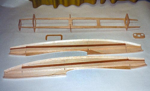 Fuselage 1: Sides and full length battery tray ready for assembly Battery tray cut from 9 ply, sides are 3mm balsa with spruce stringers and 12mm balsa triangles in corners for rounding
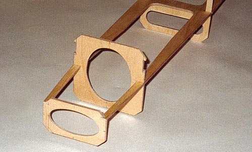 Fuselage 2 : Formers slotted into battery tray ready for sides to be glued
 Fuselage 3 : Same as above, but at rear
 Fuselage 4 " The pressure is on! Sides, tray, formers glued and clamped
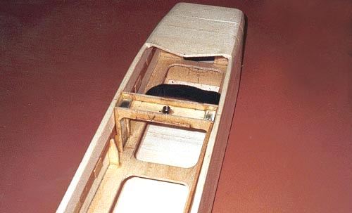
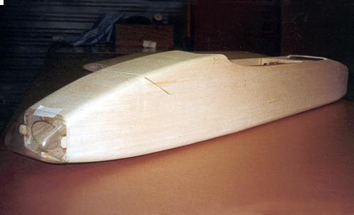 Fuselage 5 : Top and bottom sheeting (3mm) fixed and corners rounded, canopy cut and clear PVC nose cone fitted
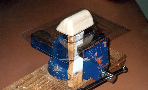 Fuselage 6 : Mould used for forming PVC nose cone. PVC is held between 2 pieces of MDF and heated in oven, when hot enough, removed from oven and forced over mould
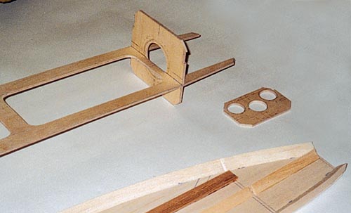
 Fuselage 7 : Bracket/mount for wing retaining bolt. Battery can be slid beneath for CG adjustment
 Fuselage 8 : Wing centre panel fitted to fuselage, held in place with 2 x _" Cap head screws
soon...
Centre panel 1 : Foam cores ready for balsa covering. Solid black lines are 14mm OD carbon fibre tubes, these are used for joining centre panel to tip panels Centre panel 2 : Foam core showing spruce spoiler bay lining. Due to torsional weakness these were later filled in Centre panel 3 : Balsa sheeting, fibre glass, carbon fibre prepared ready for laminating to foam core. This set up was used on all wing panels Centre panel 4 : L/H centre panel in vacuum bag after bonding balsa sheet to core with epoxy resin Centre panel 5 : Centre panels ready for joining. Main rib has bolt holes predrilled. Bent aluminium rod is glued into carbon tubes. Centre panel joint has glass cloth bandage applied for additional strength
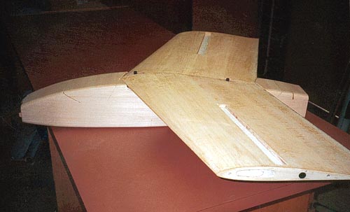
Tip panel 1 : Ply reinforcement for Elevon servo bay Tip panel 2 : Ply ribs fitted with blind nuts for bolting on tiplets Tip panel 3 : L/H Tip panel in vacuum bag after bonding balsa sheet to core with epoxy resin Tip panel 4 : Elevons cut out and faced Tip panel 5 : Finished ready for outer fibre glass skins Tip panel 6 : Tip panel jigged on workbench and covered with 3oz glass cloth Tip panel 7 : Same as above from other end Tip panel 8 : Electric blanket was used to keep cores warm during curing of epoxy
|
The term Aerobotics is © Copyright 1999-2002, CTIE
|
© Copyright 1999-2002 CTIE - All Rights Reserved - Caution
|